Device for conveying fuel

A fuel and guide device technology is applied in the field of fuel conveying devices to achieve the effect of simplifying installation and improving functions

Inactive Publication Date: 2013-07-17
ROBERT BOSCH GMBH
View PDF7 Cites 2 Cited by
  • Summary
  • Abstract
  • Description
  • Claims
  • Application Information

AI Technical Summary

Problems solved by technology

The disadvantage is that, since the compression spring is arranged between the tank flange and the cover of the storage tank,...

Method used


Image

  • Device for conveying fuel

Examples


Embodiment Construction

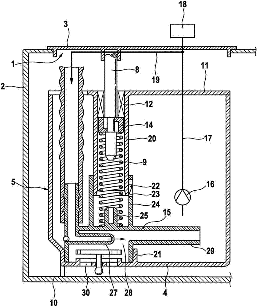
[0015] The drawing shows a simplified sectional illustration of a device according to the invention for delivering fuel, which is also referred to as a fuel delivery module.

[0016] The device for conveying fuel has a tank flange 3 closing off a tank opening 1 of a fuel tank 2 and a storage tank 5 with a tank bottom 4 . The tank flange 3 and the storage tank 5 are connected to one another via at least one guide rod 8 , wherein the storage tank 5 can be adjusted relative to the tank flange 3 along the guide rod 8 . The storage tank 5 is pressed by a spring element 9 , for example a helical compression spring, away from the tank flange 3 , so that the storage tank 5 always rests with its bottom 4 on the bottom 10 of the fuel tank 2 . The storage tank 5 has a cover 11 which is fixedly connected to the storage tank 5 and on which a bearing 12 is respectively arranged for guiding the at least one guide rod 8 . The guide rod 8 is free to move in its bearing 12 in the direction of ...


PUM


Abstract

The invention relates to a device for conveying fuel. A known device for conveying fuel has a tank flange and a storage container having a pot bottom, wherein the tank flange and the storage container are connected with each other through at least one guide rod. The storage container, along the guide rod adjustable in relation to the tank flange, is pressed by a compression spring facing away from the tank flange and has a cover. A bearing for guiding the guide rod is disposed on the cover, wherein the guide rod has a shoulder at its end facing the storage container. The disadvantage is that the compression spring and the length of the guide rod should be suitably adjusted according to the height of a fuel tank because the compression spring is disposed between the tank flange and the cover of the storage container. According to the device for conveying fuel, the adjustment of the spring element and the fuel tank at different heights can be cancelled and the same standard spring element can be used as always. According to the invention, the spring element (9) is supported with one end on the ejector (15) and with the other end on the shoulder (14) of the guide rod (8).

Description

technical field [0001] The invention relates to a device for delivering fuel. Background technique [0002] A device for conveying fuel has been known from DE 10 2007 045 178 A1, which has a tank flange and a storage tank with a tank bottom, the tank flange and the storage tank are connected to each other by at least one guide rod, wherein the storage tank The guide rod can be adjusted relative to the tank flange along the guide rod, which is pressed away from the tank flange by a compression spring, and the storage tank has a cover on which a bearing for guiding the guide rod is arranged, wherein the guide rod It has a shoulder on its end facing the storage tank. A disadvantage is that, since the compression spring is arranged between the tank flange and the lid of the storage tank, the compression spring and the length of the link must be individually adapted to the tank height of the respective fuel tank. Contents of the invention [0003] According to the invention, ...

Claims


Application Information

Patent Timeline
IPC IPC(8): F02M37/02B60K15/03
CPCB60K2015/03111B60K2015/0325F02M37/02B60K15/03F02M37/025F02M37/106
Inventor H-P·布劳恩
Owner ROBERT BOSCH GMBH
Why Eureka
Try Eureka