Filter plate component in multifunctional filter dryer

A filter dryer and multi-functional technology, which is applied in the mechanical field, can solve the problems of strengthening the filter plate assembly, deformation and failure of the filter plate assembly, etc., and achieve the effect of prolonging the service life, preventing deformation, and avoiding deformation

Active Publication Date: 2013-07-17
ZHEJIANG CHENGXIN PHARMA & CHEM EQUIP
View PDF12 Cites 10 Cited by
  • Summary
  • Abstract
  • Description
  • Claims
  • Application Information

AI Technical Summary

Problems solved by technology

[0004] The purpose of the present invention is to provide a filter plate assembly in a multi-functional filter dryer for the above-mentioned problems in the existing technology. The technical problem to be solved by the present invention is how to strengthen the strength of the filter plate assembly and prevent the deformation of the filter plate assembly. fail

Method used


Image

  • Filter plate component in multifunctional filter dryer
  • Filter plate component in multifunctional filter dryer
  • Filter plate component in multifunctional filter dryer

Examples


Embodiment 1

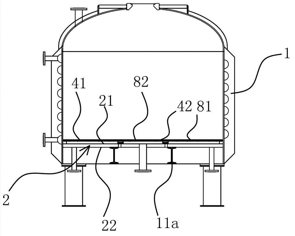
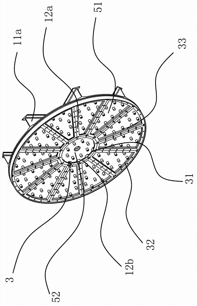
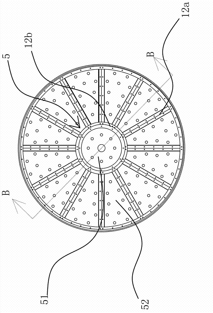
[0035] A filter plate assembly in a multifunctional filter dryer, the dryer includes a tank body 1 with a cavity inside and an open lower end, the filter plate assembly is arranged at the lower end of the tank body 1 and closes the opening of the tank body 1, the The filter plate assembly includes a bottom plate 2, a support frame 3 and several sintered plates 4. The shape of the bottom plate 2 matches the shape of the lower end section of the tank body 1. The support frame 3 is welded to the bottom plate 2. The support frame 3 has several mounting parts 5. The sintered plate 4 Welded in the installation part 5 so that the sintered plate 4 and the support frame 3 cover the bottom of the entire tank body 1, the support frame 3 includes an inner flange 31, an outer flange 32 and radially connected inner flange 31 and outer flange 32 Between the square steel 33, the mounting part 5 is surrounded by the inner flange 31, the outer flange 32 and the square steel 33. The traditional ...

Embodiment 2

[0042] The content of this embodiment is roughly the same as that of Embodiment 1, except that the positioning structure 9 includes several support plates 94 welded between the lower base plate 22 and the upper base plate 21, and the positioning structure 9 also includes several support plates welded on the upper base plate. 21 and the support plate two 95 between the fan-shaped filter plate 81 and the circular filter plate 82, the plate surface of the support plate one 94 is provided with some and through holes 96, and the support plate one 94 connects both the upper base plate 21 and the lower base plate 22 The support plate 2 95 securely connects the upper bottom plate 21 with the fan-shaped filter plate 81 and the circular filter plate 82 , and the through hole 96 provided on the support plate 1 94 facilitates the circulation of the heating medium in the heating chamber 10 .

[0043] The principle of the present invention is: in order to prevent the filter plate assembly fr...


PUM


Abstract

The invention provides a filter plate component in a multifunctional filter dryer, and belongs to the technical field of machinery. The filter plate component solves the technical problems of insufficient strength, easy deformation or failure, short service life and the like of a filter plate component in an existing filter dryer. The multifunctional filter dryer comprises a tank, a cavity is arranged inside the tank, and an opening is arranged at the lower end of the tank. The filter plate component is arranged at the lower end of the tank, closes the opening of the tank and comprises a bottom plate, a supporting frame and a plurality of sintered plates, the shape of the bottom plate is matched with the sectional shape of the lower end of the tank, the supporting frame is welded with the bottom plate and provided with a plurality of mounting portions, and the sintered plates are welded in the mounting portions, so that the sintered plates and the supporting frame cover the bottom of the whole tank. The filter plate component has the advantages of high strength, long service life and the like.

Description

technical field [0001] The invention belongs to the technical field of machinery and relates to a dryer, in particular to a filter plate assembly on a multifunctional filter dryer. Background technique [0002] The dryer generally uses steam, hot water or heat transfer oil as the heating medium, and the shaft end is equipped with a rotary joint for the introduction and export of the heat medium. The heating medium is divided into two paths, which enter the jacket of the dryer shell and the inner cavity of the paddle shaft respectively, and heat the body and the paddle shaft at the same time, and heat and dry the material by conduction heating. The material to be dried is continuously fed quantitatively into the feeding port of the dryer by the screw feeder or the reactor pump. The material enters the back of the dryer, and the material is turned over and stirred by the rotation of the paddle, and the heating interface is constantly updated, and the body and the paddle are co...

Claims


Application Information

Patent Timeline
Patent Type & Authority Applications(China)
IPC IPC(8): F26B25/10B01D29/075
Inventor 郑钦元邓军兵陈俊嘉陈仁贤
Owner ZHEJIANG CHENGXIN PHARMA & CHEM EQUIP
Why Eureka
Try Eureka