
Groove bottom surface rolling tool

A surface rolling and tooling technology, which is applied in the field of groove bottom surface rolling tools, can solve the problem that the roller cannot be submerged in the sealing groove, etc.

Active Publication Date: 2013-07-24
STATE GRID CORP OF CHINA +1
View PDF5 Cites 3 Cited by
  • Summary
  • Abstract
  • Description
  • Claims
  • Application Information

AI Technical Summary

Problems solved by technology

[0003] The object of the present invention is to provide a groove bottom surface rolling tool to solve the problem that the rollers in the prior art cannot be submerged into the seal groove to a greater depth due to the limitation of the rotating shaft

Method used


Image

  • Groove bottom surface rolling tool
  • Groove bottom surface rolling tool
  • Groove bottom surface rolling tool

Examples


Embodiment Construction

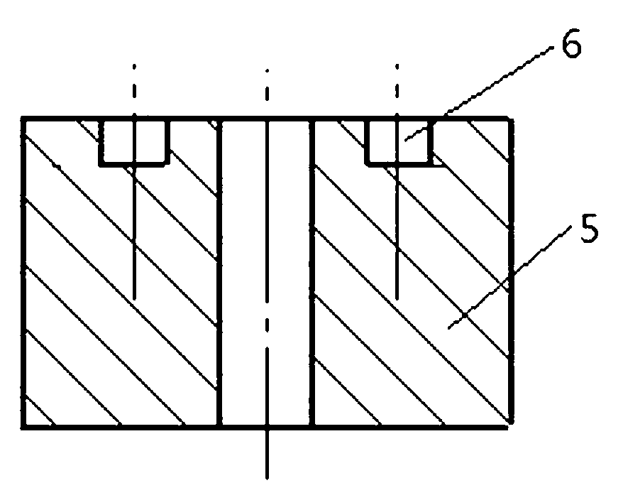
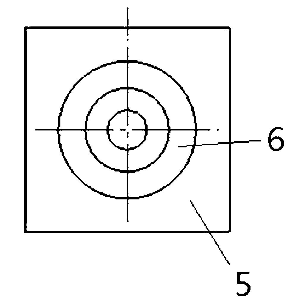
[0031] The structure of the sealing groove that needs to be rolled is as follows: Figure 2~3 As shown: the sealing groove 6 is opened on the end surface of the workpiece 5, and the groove width of the sealing groove 6 is small, and the groove bottom surface of the sealing groove 6 cannot be rolled with conventional rolling tools.

[0032] An embodiment of a groove bottom surface rolling tool is Figure 4~17Shown: including the knife rest, the knife rest includes the knife body 7 and the side support plate 8 and the stop piece 9 fixed on the lower end of the knife body 7 from left to right through the fixed connection structure. The fixed connection structure includes realizing the side support plate 8 and the stop piece respectively Sheet 9 and cutter body 7 positioning pins 12 and connecting screws 11 for positioning assembly and fixed assembly, side support plate 8, retaining plate 9 and cutter body 7 are all provided with positioning holes that are matched with positioning...


PUM


Abstract

The invention relates to a groove bottom surface rolling tool which comprises a knife rest and a pin roller with a tapered circumferential surface, wherein the lower end of the knife rest is provided with a pin roller accommodating groove provided with a downward notch, the pin roller is rotatably assembled in the pin roller accommodating groove, the pin roller accommodating groove is provided with a groove wall which is matched with the outer circumferential surface of the pin roller in a radial limiting manner so as to prevent the pin roller from escaping from the pin roller accommodating groove, the outer circumferential surface of the pin roller protrudes out of the notch of the pin roller accommodating groove, a first axial limiting structure and a second axial limiting structure which are respectively matched with two axial ends of the pin roller in a limiting manner are arranged on the knife rest, at least two support rollers which are circumferentially distributed around the pin roller are rotatably assembled on the knife rest and positioned above the pin roller, the rotating axis of each support roller is respectively parallel to that of the pin roller, and the outer circumferential surface of each support roller is respectively in friction rolling fit with the outer circumferential surface of the pin roller in an adaptive support manner. According to the groove bottom surface rolling tool, the problem that the pin roller cannot be immersed into a sealing groove to a larger depth due to the limit of a rotating shaft in the prior art is solved.

Description

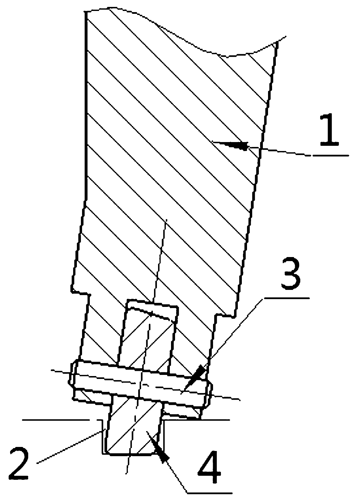
technical field [0001] The invention relates to a groove bottom surface rolling tool used for groove bottom surface rolling processing. Background technique [0002] In the field of machining, it is often encountered that the bottom surface of the end seal groove is rolled. Since the seal ring needs to be installed in the end seal groove, the smoothness of the bottom surface of the end seal groove has a great influence on the sealing effect of the seal ring. influences. The existing processing form is to use a rolling tool to roll the bottom surface of the sealing groove. The specific structure of the rolling tool is as follows: figure 1 As shown: the rolling tool includes a cutter body 1, and the lower part of the cutter body 1 is rotated by a pin shaft 3 to be equipped with a roller 4 with a tapered outer peripheral surface. When in use, the tapered outer peripheral surface of the roller 4 rolls the corresponding sealing groove 2. The bottom surface of the groove, so tha...

Claims


Application Information

Patent Timeline
IPC IPC(8): B23P9/02
Inventor 张子明董长利杨继春符严平
Owner STATE GRID CORP OF CHINA
Learn More