
Redundant communication reception management system and method of time-triggered Ethernet end node

A time-triggered, redundant communication technology, which is applied in the field of redundant communication receiving management system, can solve problems such as complex timing, difficult receiving redundant processing, and no public time-triggered redundant communication receiving management method for Ethernet end nodes. , to achieve the effect of improving execution efficiency and simplifying design

Active Publication Date: 2019-03-01
XIAN MICROELECTRONICS TECH INST
View PDF8 Cites 3 Cited by
  • Summary
  • Abstract
  • Description
  • Claims
  • Application Information

AI Technical Summary

Problems solved by technology

Due to the concurrent transmission characteristics of time-triggered data, the timing of redundant messages arriving at the receiving node in multiple channels is complicated, and it is difficult to process redundant reception.
[0003] None of the existing methods for redundant communication management in the Ethernet field are suitable for time-triggered Ethernet receive management.
In the data communication method based on redundant network disclosed in Chinese patent CN200410042985.0, network nodes are required to periodically send network diagnostic information, maintain a network status information table, and determine an optimal path for redundant message transmission according to the network status; In the reception of redundant and non-redundant messages disclosed in Chinese patent CN200580038914.6, the given method for judging the reception of valid messages and redundant messages in redundant links has no time window check and no specific reception Management mode, not suitable for reception management of time-critical time-triggered Ethernet
For the reception management of time-triggered Ethernet, there is currently no public method for redundant communication reception management of time-triggered Ethernet end nodes

Method used


Image

  • Redundant communication reception management system and method of time-triggered Ethernet end node
  • Redundant communication reception management system and method of time-triggered Ethernet end node
  • Redundant communication reception management system and method of time-triggered Ethernet end node

Examples


Embodiment Construction

[0045] In order to enable those skilled in the art to better understand the solutions of the present invention, the following will clearly and completely describe the technical solutions in the embodiments of the present invention in conjunction with the drawings in the embodiments of the present invention. Obviously, the described embodiments are only It is an embodiment of a part of the present invention, but not all embodiments. Based on the embodiments of the present invention, all other embodiments obtained by persons of ordinary skill in the art without making creative efforts shall fall within the protection scope of the present invention.

[0046] It should be noted that the terms "first" and "second" in the description and claims of the present invention and the above drawings are used to distinguish similar objects, but not necessarily used to describe a specific sequence or sequence. It is to be understood that the data so used are interchangeable under appropriate ...


PUM


Abstract

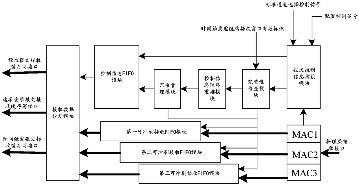
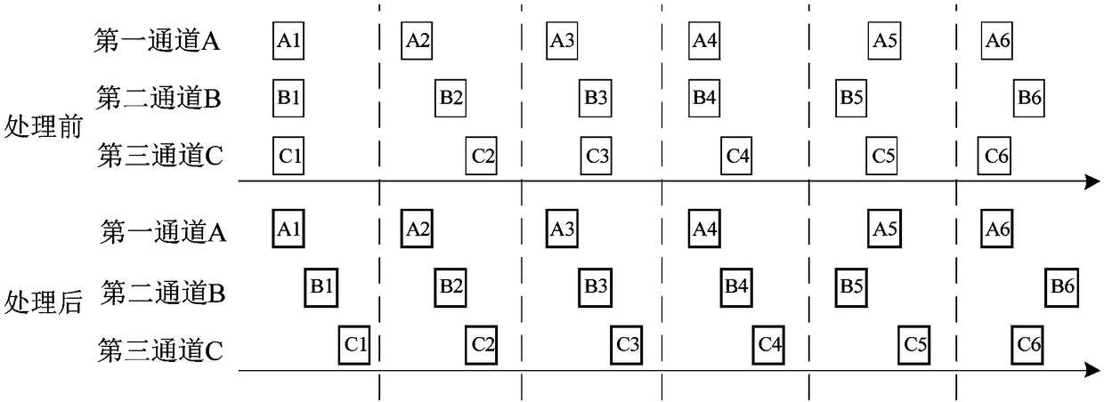
The invention discloses a redundant communication reception management system and method of a time-triggered Ethernet end node. The system comprises a message control information capturing module, anintegrity inspection module, a control information time sequence re-arrangement module, a redundancy management module, a control information FIFO module, a washable reception FIFO module and a reception data distribution module. The method includes a reception management method of time-triggered / rate-restricted message data and standard message data. According to the system and the method, the sequence integrity inspection of a received message is accomplished, the time integrity inspection of a time-triggered network message is also accomplished, and functions can be configured; through timesequence re-arrangement of the network message, the design of the redundancy management module is simplified, redundancy management of network messages of a single channel, double channels, three channels and more channels can be adaptive supported, and redundant frames and non-redundant frames can be effectively distinguished and processed; besides, the washable reception FIFO buffering mode isadopted so that assembly-line type message data processing is realized, and the execution efficiency is high.

Description

technical field [0001] The invention belongs to the field of multi-channel redundant communication receiving data management, and relates to a time-triggered redundant communication receiving management system and method for Ethernet end nodes. Background technique [0002] Time-triggered Ethernet is formed on the basis of IEEE802.3 standard Ethernet technology by adding technologies such as distributed network clock synchronization, time-triggered communication and reliability assurance. Time-triggered Ethernet supports dual-redundant or triple-redundant communication. Redundant communication runs on multiple independent physical links. Through adaptive transformation of the data link layer, a unified data interface is provided for the communication link of the upper layer protocol. . Due to the concurrent transmission characteristics of time-triggered data, the time sequence of multiple channel redundant messages arriving at the receiving node is complicated, and the proc...

Claims


Application Information

Patent Timeline
Patent Type & Authority Applications(China)
IPC IPC(8): H04L12/823H04L12/861H04L47/32
CPCH04L47/32H04L49/90
Inventor 唐金锋刘露徐丹妮郑堃唐雷雷
Owner XIAN MICROELECTRONICS TECH INST
Learn More