Packing box structure

A packing box and side panel technology, applied in packaging, transportation and packaging, rigid containers, etc., can solve the problems of wasting wood, destroying the natural environment, increasing production costs, etc., and achieve the effect of reducing waste and reducing production costs

Inactive Publication Date: 2013-07-24
无锡市安托包装材料有限公司
View PDF6 Cites 5 Cited by
  • Summary
  • Abstract
  • Description
  • Claims
  • Application Information

AI Technical Summary

Problems solved by technology

[0002] The adjacent side panels and the base of the existing packaging boxes are fixedly connected. When the goods in the packaging box need to be taken out, the side panels of the packaging box must be destructively disassembled. The usual packaging boxes cannot be reused. The production of raw materials causes a large waste and increases the production cost, especially wooden packaging boxes, which need to waste a lot of wood. For a large number of wood felling, it will cause ecological imbalance and seriously damage the natural environment in which we live. , affecting the sustainable development of society

Method used


Image

  • Packing box structure
  • Packing box structure
  • Packing box structure

Examples


Embodiment 1

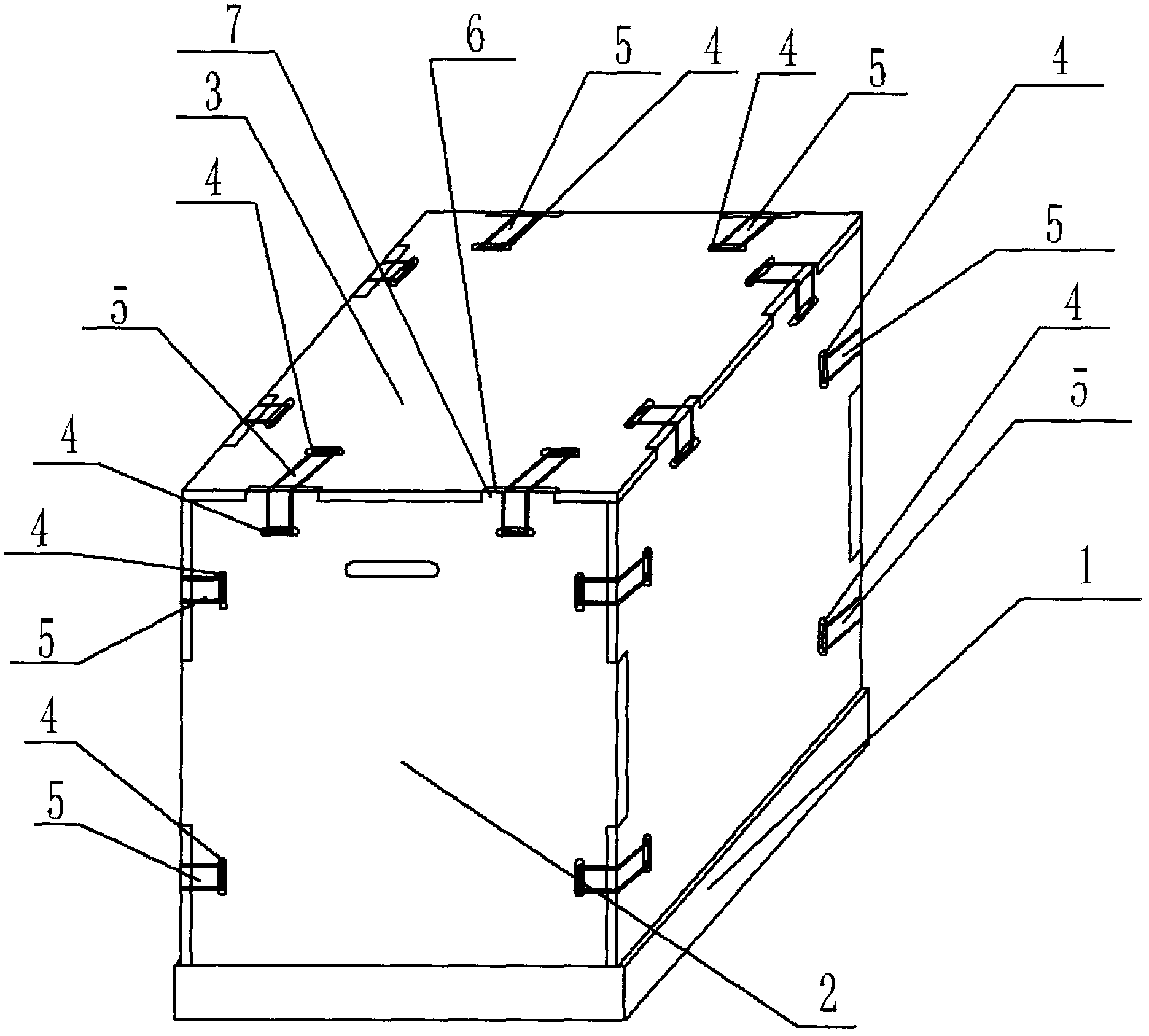
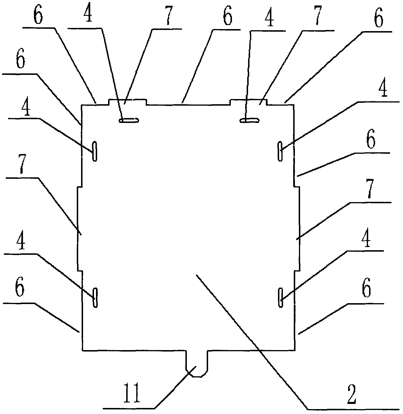
[0016] Example one, see figure 2 , image 3 with Figure 5 , The base 1 is provided with a bottom plate 8, a T-shaped groove 9 is provided on the side of the bottom plate 8, a pair of opposite side plates 2 are provided with a T-shaped connecting rod 10 that matches the T-shaped groove 9, and the T-shaped connecting rod 10 is inserted into the T The groove 9 moves to the outside of the bottom plate to realize the stable and detachable clamping connection between the side plate 2 and the bottom plate 8. The other pair of opposite side plates 2 are provided with positioning rods 11 that cooperate with the T-shaped groove 9 to ensure the side plates. 2. Positioning.

Embodiment 2

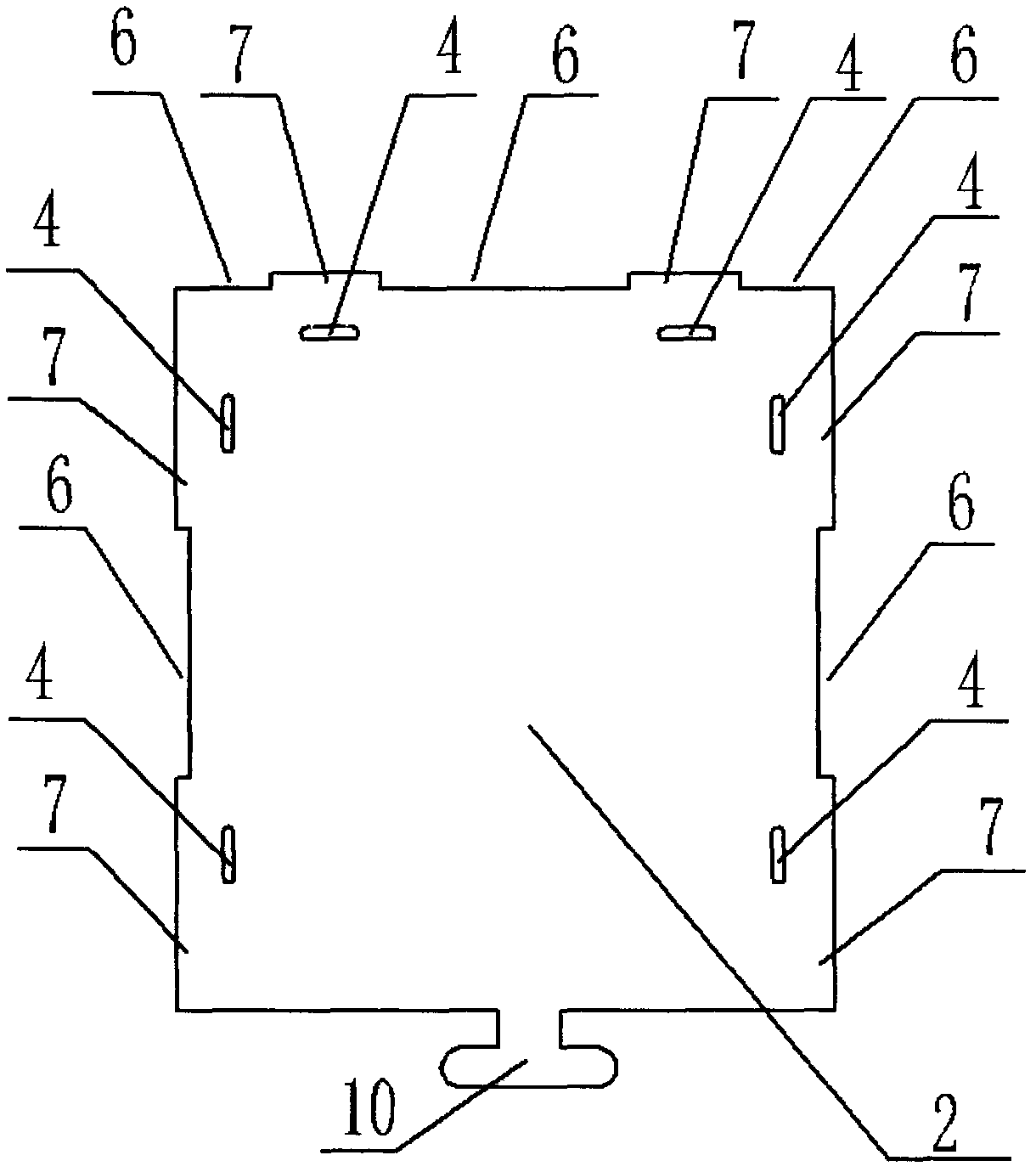
[0017] Example two, see figure 2 , Image 6 with Figure 7 , The base 1 is provided with a bottom plate 8, a positioning groove 13 is provided on the side of the bottom plate 8, a positioning rod 11 matching the positioning groove 13 is provided on the side plate 2, and a pair of positioning rods 11 are provided with a positioning groove 13 The matching positioning circlip 12, after the positioning circlip 12 is inserted into the positioning slot 13, realizes the stable and detachable snap connection between the side plate 2 and the bottom plate 8. In order to facilitate processing and the versatility of the positioning groove in the structure of the positioning groove, the positioning groove in the second embodiment can also be added to the T-shaped groove in the first embodiment to realize the versatility of the positioning groove and the unity of processing.


PUM


Abstract

The invention provides a packing box structure. By the packing box structure, a packing box which is used for packing goods can be reused, so that the raw materials of the packing box are not wasted, and the production cost is reduced. The packing box structure comprises a base, side plates and a cover plate, and is characterized in that the side plates are movably and detachably connected with the base; the adjacent side plates are correspondingly provided with bayonets; the side plates and the cover plate are correspondingly provided with bayonets; the corresponding bayonets of the adjacent side plates are connected by detachable snap joints; and the corresponding bayonets of the side plates and the cover plate are connected by detachable snap joints.

Description

Technical field [0001] The invention relates to the technical field of article packaging appliances, in particular to a packaging box structure. Background technique [0002] The adjacent side panels and the base of the existing packaging box are all fixedly connected. When the goods in the packaging box need to be taken out, the side panels of the packaging box must be destructively disassembled. The usual packaging boxes cannot be reused. The production of raw materials caused large waste and increased production costs, especially wooden packaging boxes, which required a large amount of wood to be wasted. For a large number of logging of wood, it will cause ecological imbalance and seriously damage our natural environment. , Affecting the sustainable development of society. Summary of the invention [0003] In view of the above-mentioned problems, the present invention provides a packaging box structure, which can make the packaging box of the packaged goods be reused, reduce t...

Claims


Application Information

Patent Timeline
IPC IPC(8): B65D6/24
Inventor 文世根
Owner 无锡市安托包装材料有限公司
Why Eureka
Try Eureka