
Clamping mechanism for SMT screen plate measurement

A technology of clamping mechanism and stencil, applied in the direction of measuring devices, instruments, etc., can solve the problems of high overall cost of the experimental plan, inconvenient operation, deformation of stencil, etc., and achieve the effect of ensuring the accuracy of repeated measurement

Inactive Publication Date: 2013-07-24
KUNSHAN THETA MICRO
View PDF5 Cites 0 Cited by
  • Summary
  • Abstract
  • Description
  • Claims
  • Application Information

AI Technical Summary

Problems solved by technology

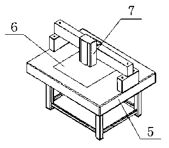
This method has the following defects: 1) Since the positioning surface is slightly higher than the measurement platform, and the adsorption holes are distributed on the measurement plane around the positioning surface, and the stencil has high flexibility, the stencil at the measurement point will inevitably be arched after adsorption. There is a risk of local deformation of the stencil; 2) It is difficult to accurately control the height of the stencils with different thicknesses, which seriously affects the accuracy of repeated measurement; 3) It is difficult for the three steel balls to ensure that the positioning surface formed by their respective highest points is completely horizontal (and the surface It needs to be perpendicular to the vertical movement direction of the probe); 4) High requirements are placed on the accuracy of the three steel balls, the overall cost of the experimental scheme is high, and the operation is inconvenient

Method used


Image

  • Clamping mechanism for SMT screen plate measurement
  • Clamping mechanism for SMT screen plate measurement
  • Clamping mechanism for SMT screen plate measurement

Examples


Embodiment Construction

[0034] In order to make the technical means, creative features, goals and effects achieved by the present invention easy to understand, the present invention will be further described below in conjunction with specific diagrams.

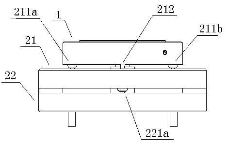
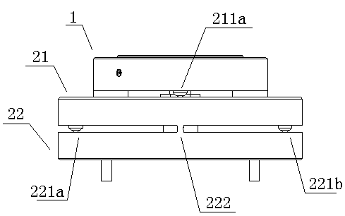
[0035] refer to Figure 4 , a clamping mechanism applied to the measurement of SMT stencils, including a fixed seat 1, a positioning hole penetrating the thickness of the fixed seat 1 is opened on the fixed seat 1, and a two-dimensional degree of freedom adjustment mechanism 2, two-dimensional freedom The degree adjustment mechanism 2 is arranged under the fixed seat 1, and is used for adjusting the left-right inclination and the front-rear inclination of the fixed seat 1. After the present invention is fixed directly under the vertical side head, through the adjustment function of the two-dimensional degree of freedom adjustment mechanism 2, the working surface of the clamping mechanism, that is, the upper surface of the fixing seat 1 is adjusted to...


PUM


Abstract

The invention relates to the field of SMT equipment application, in particular to a clamping and fastening device. A clamping mechanism for SMT screen plate measurement comprises a fixed seat, a locating hole penetrating through the thickness of the fixed seat is formed in the fixed seat, and the clamping mechanism for SMT screen plate measurement further comprises a two-dimensional freedom degree adjusting mechanism. The two-dimensional freedom degree adjusting mechanism is arranged below the fixed seat, and is used for adjusting lift-and-right inclination and front-and-back inclination of the fixed seat. Due to the fact that the mentioned technical scheme is adopted, through an accurate two-dimensional angle adjusting function, the clamping mechanism for SMT screen plate measurement can adjust the working surface of the fixed seat to be perpendicular to the vertical moving direction of a vertical type measuring head conveniently, and guarantee full attachment of a screen plate and the working surface of the clamping mechanism in a measuring process, and repeated measurement accuracy of the screen plate is guaranteed to be in + / - 1 micron.

Description

[0001] technical field [0002] The invention relates to the application field of SMT equipment, in particular to a clamping and fixing device. [0003] Background technique [0004] In the SMT field, the measurement of incoming stencils has become a key process to ensure the quality of SMT subsequent processing. The thickness of SMT incoming stencil is generally below 0.3mm, and the format is usually above 400mmx400mm. This kind of stencil has the characteristics of thin material, high precision, large format and high flexibility. As the market's requirements for the processing efficiency and cost of SMT stencils gradually increase, the format of SMT stencils is getting larger and larger. [0005] In the past SMT stencil measurement equipment, the stencil was often placed directly on the measurement equipment platform, such as figure 1 As shown, the flatness of the measuring equipment platform 5 itself is used to ensure the flatness of the stencil 6 placed on the platfor...

Claims


Application Information

Patent Timeline
IPC IPC(8): G01B21/08
Inventor 魏志凌宁军夏发平
Owner KUNSHAN THETA MICRO
Learn More