Pulsar accumulated pulse profile time delay measurement method by sparse representation

A technology of accumulating pulse and time delay, applied in the field of signal processing, can solve the problems of poor sparse representation effect and inability to achieve sparse representation effect, etc., and achieves a small amount of computation, high accumulative pulse profile time delay measurement accuracy, and improved navigation accuracy. Effect

Inactive Publication Date: 2013-07-24
XIDIAN UNIV
View PDF2 Cites 17 Cited by
  • Summary
  • Abstract
  • Description
  • Claims
  • Application Information

AI Technical Summary

Benefits of technology

This patented technology improves upon previous methods for measuring pulser timing accurately due to its ability to use an improved way to match two different signals together without affecting their quality or precision level. It also reduces errors caused during measurements over longer periods compared to older techniques such as correlation between multiple sensors. Overall, this new technique provides more accurate data from long duration events like laser ranging systems (LAR).

Problems solved by technology

The technical problem addressed in this patents relates to the challenge of efficiently analyzing precise measurements made through x ray burst imagers while minimizing errors caused by variations in radiation intensity due to temperature fluctuations during scanning. Existing solutions involve complex calculations involving multiple variables like integration times between two sets of radons, leading to increased computation costs.

Method used


Image

  • Pulsar accumulated pulse profile time delay measurement method by sparse representation
  • Pulsar accumulated pulse profile time delay measurement method by sparse representation
  • Pulsar accumulated pulse profile time delay measurement method by sparse representation

Examples


Embodiment Construction

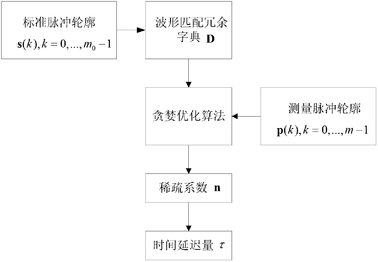
[0027] refer to figure 1 , the specific implementation steps of the present invention are as follows:

[0028] Step 1. Enter the phase interval as m 0 The standard pulse profile of the standard pulse profile is sampled to construct a waveform matching redundancy dictionary D.

[0029] (1a) Let the standard pulse profile s(k),k=0,...,m 0 The phase corresponding to s(0) in -1 is i=0;

[0030] (1b) With the standard pulse profile s(k),k=0,...,m 0 The point corresponding to phase i in -1 is the starting point, and the sampling rate is Sampling the standard pulse profile at the sampling frequency to obtain m sampling points, namely

[0031]

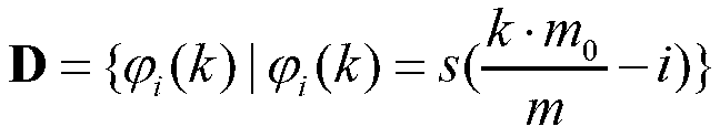
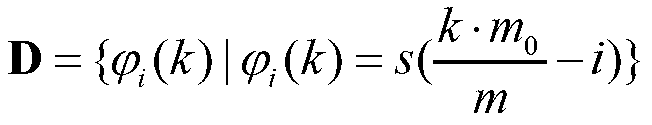
[0032] (1c) Let i=i+1, repeat step (1b) until i=m 0 , the waveform matching redundancy dictionary is obtained as:

[0033]

[0034] Among them, i=0,1,2,…,m 0 -1, k=0,1,2,...,m-1.

[0035] Step 2. A greedy optimization algorithm is used to calculate the first-order sparse coefficient vector of the measured pulse profile under the ...


PUM


Abstract

The invention discloses an accumulated pulse profile time delay measurement method by sparse representation, and aims to mainly solve the problem that the sampling frequency and signal to noise ratio of pulse profiles can affect measurement accuracy in the prior art. The method is realized by the steps of: (1) conducting standard pulse profile sampling, and constructing a waveform matching redundant dictionary; (2) employing a greedy optimization algorithm to calculate a first-order sparse coefficient vector of the measurement pulse profile under the waveform matching redundant dictionary; and (3) according to the column corresponding to the only nonzero element in the first-order sparse coefficient vector, calculating the accumulated pulse profile time delay. Compared with the prior art, the method provided in the invention significantly reduces computation, improves the measurement precision of time delay, shortens the pulse profile accumulation time, and can be used for measurement of the time difference of arrival (TDOA) of the pulse from a spacecraft to a solar system barycenter.

Description


Claims


Application Information

Patent Timeline
Owner XIDIAN UNIV
Why Eureka
Try Eureka