
Pressure sensor

A pressure sensor and pressure technology, applied in the direction of measuring fluid pressure, instruments, fluid pressure measurement using capacitance changes, etc., can solve problems such as stick-slip, affecting pressure measurement accuracy, and different degrees of expansion, so as to eliminate relative displacement and reduce Difficulty of processing, effect of homogenization of action

Pending Publication Date: 2022-02-25
BEIJING SEVENSTAR FLOW CO LTD
View PDF0 Cites 2 Cited by
  • Summary
  • Abstract
  • Description
  • Claims
  • Application Information

AI Technical Summary

Problems solved by technology

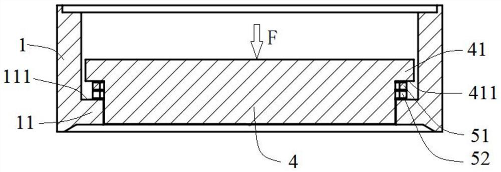
[0006] There are usually steps on the inner wall of the upper support to support the electrode parts. However, since the electrode parts are insulators (such as ceramics) and the upper support is metal, the thermal expansion coefficient of the upper support is greater than that of the insulator. When the temperature changes, the degree of expansion of the two is different, so a stick-slip phenomenon may occur between the two, and then a certain relative displacement will occur.
Although after the temperature returns to the original value, the relative position of the two will roughly return to the original state, but there are very small differences, and these differences will affect the relative position between the electrode part and the moving membrane , which in turn affects the measurement accuracy of the final pressure

Method used


Image

  • Pressure sensor
  • Pressure sensor
  • Pressure sensor

Examples


Embodiment Construction

[0030] In order to enable those skilled in the art to better understand the technical solution of the present invention, the pressure sensor provided by the present invention will be described in detail below with reference to the accompanying drawings.

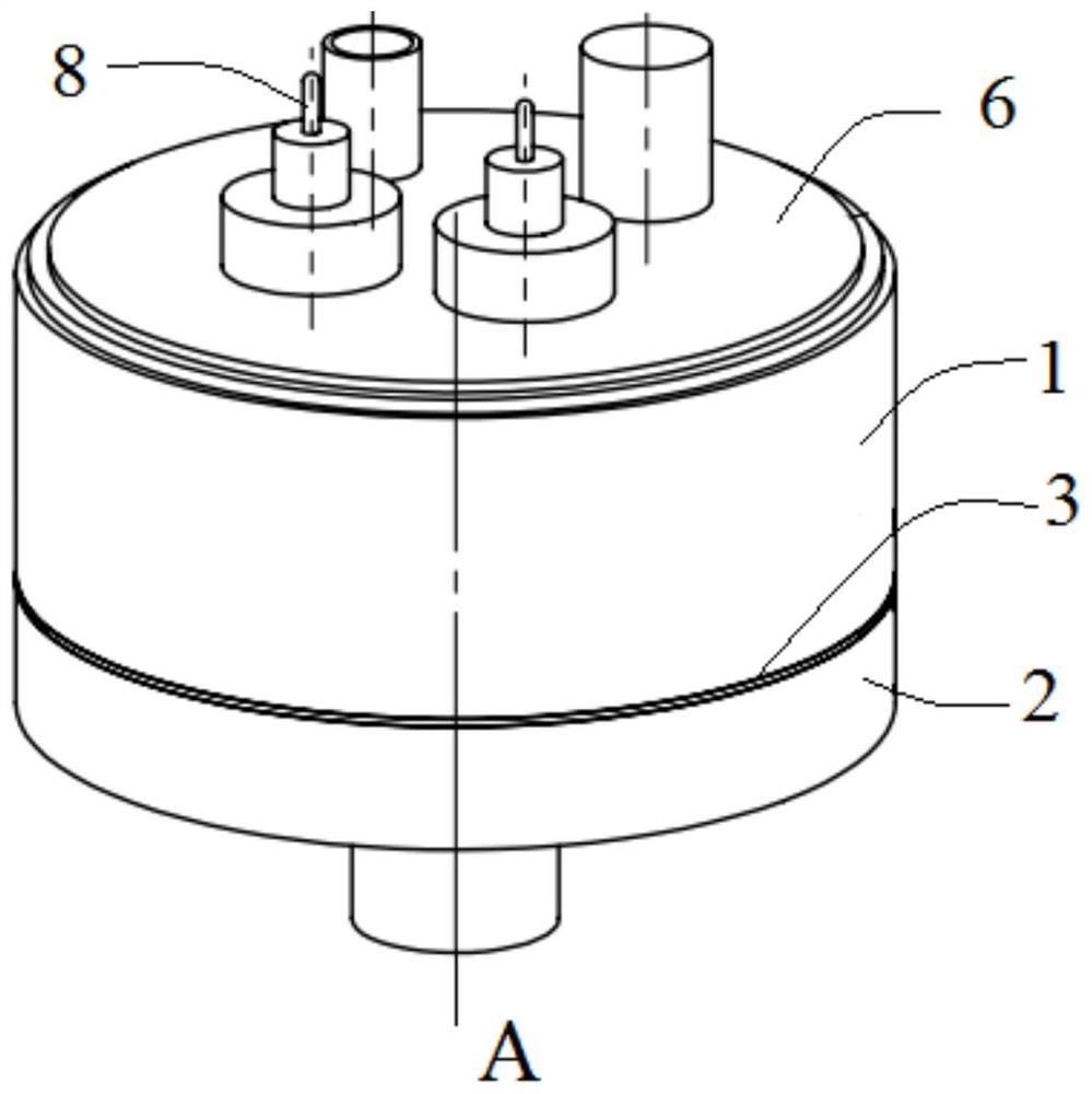
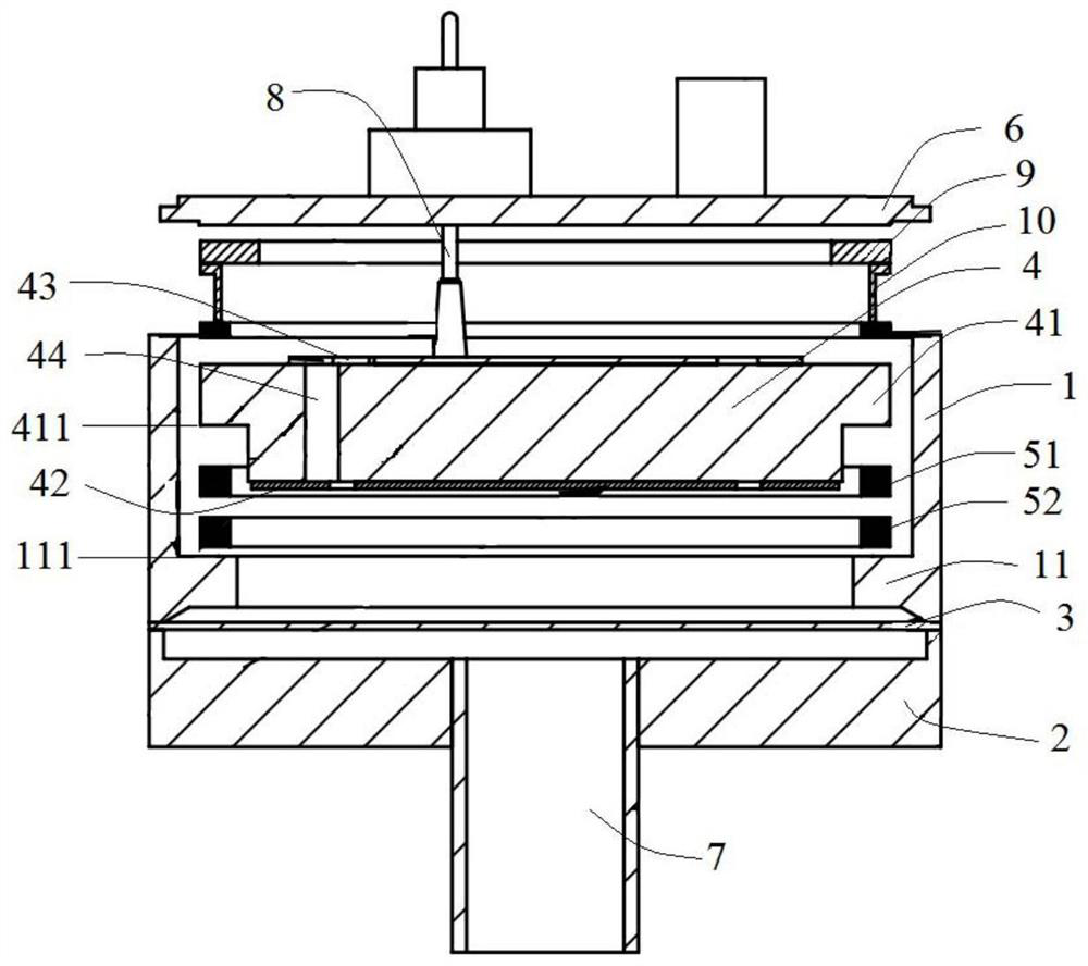
[0031] Please also refer to figure 1 and figure 2 , the pressure sensor provided by the embodiment of the present invention includes a first support 1, a second support 2, a moving membrane 3, an electrode part 4, two adjustment parts (51, 52), a top cover 6, a pipeline 7, Wire 8, elastic member 9 and support ring 10. Among them, the first support 1, the moving film 3 and the second support 2 are along the figure 1 The axis A of the medium pressure sensor is arranged sequentially from top to bottom, and all three are made of conductive metal materials, and are connected together by means of welding or the like. And, the top of the first support 1 is provided with a top cover 6, in order to seal the top opening of the firs...


PUM

PropertyMeasurementUnit
shear modulusaaaaaaaaaa
elastic modulusaaaaaaaaaa

Abstract

The invention provides a pressure sensor, which comprises a first support and an electrode piece, and is characterized in that the first support is provided with a supporting part used for supporting the electrode piece, and a plurality of adjusting pieces are sequentially superposed between two opposite surfaces of the electrode piece and the supporting part; the thermal expansion coefficients of the electrode piece, the multiple adjusting pieces and the first support are gradually increased one by one in the direction from the electrode piece to the supporting part. According to the pressure sensor provided by the invention, the problem of relative displacement between parts caused by temperature change can be solved.

Description

technical field [0001] The invention relates to the field of semiconductor manufacturing, in particular to a pressure sensor. Background technique [0002] In the field of semiconductors, when etching and other methods are used to produce chips, it is usually required to monitor the pressure of the process gas with high precision, so as to accurately control the pressure and flow of the gas, so as to produce high-quality products. [0003] The existing pressure sensor includes an upper support, an electrode part, a lower support and a moving membrane, wherein the upper support, the moving membrane and the lower support are stacked in sequence, and all three are metal conductor parts, and are connected by welding or the like. Together, wherein the top opening of the upper support is provided with a top cover, the upper space is formed between the top cover, the moving film and the upper support, the lower space is formed between the moving film and the lower support, and the ...

Claims


Application Information

Patent Timeline
Patent Type & Authority Applications(China)
IPC IPC(8): G01L9/12G01L19/00
CPCG01L9/12G01L19/00
Inventor 张锋胡蕾
Owner BEIJING SEVENSTAR FLOW CO LTD
Learn More