Time-delay measurement method for pulsar cumulative pulse profile using sparse representation

A technique of accumulating pulses and time delays, which is applied in the field of signal processing, can solve problems such as inability to achieve sparse representation effects, poor sparse representation effects, etc., achieve high accumulative pulse profile time delay measurement accuracy, small amount of calculation, and improve navigation accuracy Effect

Inactive Publication Date: 2015-11-11
XIDIAN UNIV
View PDF2 Cites 1 Cited by
  • Summary
  • Abstract
  • Description
  • Claims
  • Application Information

AI Technical Summary

Problems solved by technology

The traditional signal sparse representation method based on "basis" has certain limitations and cannot achieve a good sparse representation effect, especially for signals with a wide range of frequency changes, the sparse representation effect is even worse

Method used


Image

  • Time-delay measurement method for pulsar cumulative pulse profile using sparse representation
  • Time-delay measurement method for pulsar cumulative pulse profile using sparse representation
  • Time-delay measurement method for pulsar cumulative pulse profile using sparse representation

Examples


Embodiment Construction

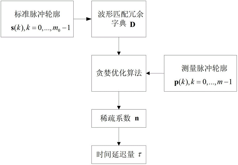
[0027] refer to figure 1 , the specific implementation steps of the present invention are as follows:

[0028] Step 1. Enter the phase interval as m 0 The standard pulse profile of the standard pulse profile is sampled to construct a waveform matching redundancy dictionary D.

[0029] (1a) Let the standard pulse profile s(k),k=0,...,m 0 The phase corresponding to s(0) in -1 is i=0;

[0030] (1b) With the standard pulse profile s(k),k=0,...,m 0 The point corresponding to phase i in -1 is the starting point, and the sampling rate is Sampling the standard pulse profile at the sampling frequency to obtain m sampling points, namely

[0031]

[0032] (1c) Let i=i+1, repeat step (1b) until i=m 0 , the waveform matching redundancy dictionary is obtained as:

[0033]

[0034] Among them, i=0,1,2,…,m 0-1, k=0,1,2,...,m-1.

[0035] Step 2. A greedy optimization algorithm is used to calculate the first-order sparse coefficient vector of the measured pulse profile under the...


PUM


Abstract

The invention discloses an accumulated pulse profile time delay measurement method by sparse representation, and aims to mainly solve the problem that the sampling frequency and signal to noise ratio of pulse profiles can affect measurement accuracy in the prior art. The method is realized by the steps of: (1) conducting standard pulse profile sampling, and constructing a waveform matching redundant dictionary; (2) employing a greedy optimization algorithm to calculate a first-order sparse coefficient vector of the measurement pulse profile under the waveform matching redundant dictionary; and (3) according to the column corresponding to the only nonzero element in the first-order sparse coefficient vector, calculating the accumulated pulse profile time delay. Compared with the prior art, the method provided in the invention significantly reduces computation, improves the measurement precision of time delay, shortens the pulse profile accumulation time, and can be used for measurement of the time difference of arrival (TDOA) of the pulse from a spacecraft to a solar system barycenter.

Description

technical field [0001] The invention belongs to the technical field of signal processing, and relates to a method for measuring the time delay of pulsar cumulative pulse contours, which can be used for X-ray pulsar navigation. Background technique [0002] X-ray pulsar navigation can provide accurate position, velocity, attitude time and other navigation information for low-earth orbit satellites, interstellar spacecraft and deep space probes, and is not easy to be interfered, so it has broad application prospects and value. [0003] The basic observation of the X-ray pulsar navigation system is the time difference of arrival (TDOA) of pulsar cumulative pulses from the spacecraft to the center of mass of the solar system. In addition to the resolution of the X-ray detector and the accuracy of the time conversion model, the time delay of the measured pulse profile relative to the standard pulse profile, that is, the time delay of the accumulated pulse profile is a key factor ...

Claims


Application Information

Patent Timeline
Patent Type & Authority Patents(China)
IPC IPC(8): G01C21/24
Inventor 冯冬竹袁晓光何晓川郭鹤鹤孙景荣许录平付达
Owner XIDIAN UNIV
Why Eureka
Try Eureka