Fault diagnosis system and diagnosis method thereof for optical fiber current sensor

A technology for sensor failure and fiber optic current, which is applied in instruments, measuring electrical variables, measuring devices, etc., and can solve the problems of optical path loss, change, and strength affecting the accuracy of the current value measured by the sensor.

Active Publication Date: 2020-03-24
XI AN JIAOTONG UNIV
View PDF9 Cites 2 Cited by
  • Summary
  • Abstract
  • Description
  • Claims
  • Application Information

AI Technical Summary

Problems solved by technology

In the actual application of fiber optic current sensors, the strength of the optical signal affects the accuracy of the sensor's measured current value. The optical signal transmitted in the optical fiber will inevitably attenuate due to optical path loss, or change due to temperature changes, and even cause the fiber to break. When the optical signal cannot be transmitted, some of the errors in the current measurement value caused by these factors are within the normal range, such as the loss of the optical path;

Method used


Image

  • Fault diagnosis system and diagnosis method thereof for optical fiber current sensor
  • Fault diagnosis system and diagnosis method thereof for optical fiber current sensor
  • Fault diagnosis system and diagnosis method thereof for optical fiber current sensor

Examples


Embodiment Construction

[0033] Attached below Figure 1 to Figure 7 The technical scheme of the present disclosure is described in detail with the examples.

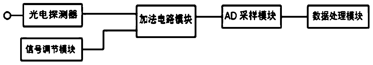
[0034] In one embodiment, such as figure 1 As shown, the present disclosure provides a fiber optic current sensor fault diagnosis system, including:

[0035] A photodetector is used to convert the light intensity signal transmitted by the fiber optic current sensor into an electrical signal;

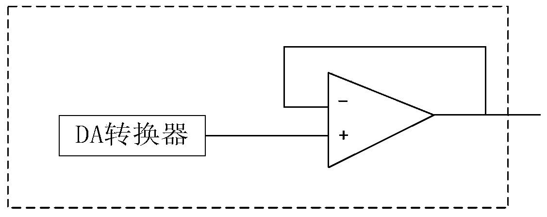
[0036] A signal conditioning module, configured to output an adjustable DC bias electrical signal;

[0037] An adding circuit module, configured to add the electrical signal output by the photodetector and the DC bias electrical signal output by the signal adjustment module to output a mixed signal;

[0038] AD sampling module, for sampling two adjacent half-period analog signals in the mixed signal and converting them into two adjacent half-period digital signals;

[0039] The data processing module is used to receive the two adjacent half-period dig...


PUM


Abstract

The invention discloses a fault diagnosis system for an optical fiber current sensor. The fault diagnosis system comprises a photoelectric detector, a signal conditioning module, an adder circuit module, an AD sampling module and a data processing module. The invention further discloses a fault diagnosis method for the optical fiber current sensor. The system can be used for detecting whether thewhole optical path system of the optical fiber current sensor fails or not; the fault detection system is established on the basis of an optical fiber current sensor measurement system without extra circuit components and systems and extra optical path loss, so that the measurement precision and the like of the optical fiber current sensor are not affected, and effective detection of optical fibercurrent sensor faults can be completed under the conditions of low cost and easy implementation.

Description

technical field [0001] The disclosure belongs to the field of optical fiber current sensors, and in particular relates to a fault diagnosis system and a diagnosis method for an optical fiber current sensor. Background technique [0002] The rapid development of modern industry has put forward higher requirements for the transmission and detection of the power grid, and the traditional high-voltage and high-current measurement methods will face severe tests. With the development of optical fiber technology and material science, the optical fiber current sensing system has a series of advantages due to its good insulation and anti-interference ability, high measurement accuracy, easy miniaturization, and no potential explosion hazard. Sexuality is widely valued by people. In order to ensure the long-term normal and stable operation of the fiber optic current sensor, it is necessary to study the fault detection system of the fiber optic current sensor. In the actual applicati...

Claims


Application Information

Patent Timeline
Patent Type & Authority Applications(China)
IPC IPC(8): G01R35/00
CPCG01R35/00
Inventor 姬忠校刘美刁兆炜吴益飞吴翊杨飞牛立壮
Owner XI AN JIAOTONG UNIV
Why Eureka
Try Eureka