Backlight module and display device comprising same

A backlight module and display device technology, applied in lighting devices, fixed lighting devices, lighting auxiliary devices, etc., can solve problems such as image distortion, and achieve the effect of solving uneven brightness

Inactive Publication Date: 2013-07-31
INNOCOM TECH SHENZHEN +1
View PDF7 Cites 4 Cited by
  • Summary
  • Abstract
  • Description
  • Claims
  • Application Information

AI Technical Summary

Problems solved by technology

like figure 1 As shown, due to the relative position between the support member 51 and its surrounding light source 52 or the brightness difference between the support member 51 and the surroundin

Method used


Image

  • Backlight module and display device comprising same
  • Backlight module and display device comprising same
  • Backlight module and display device comprising same

Examples


Embodiment Construction

[0107] The preferred embodiment is now described in conjunction with the accompanying drawings.

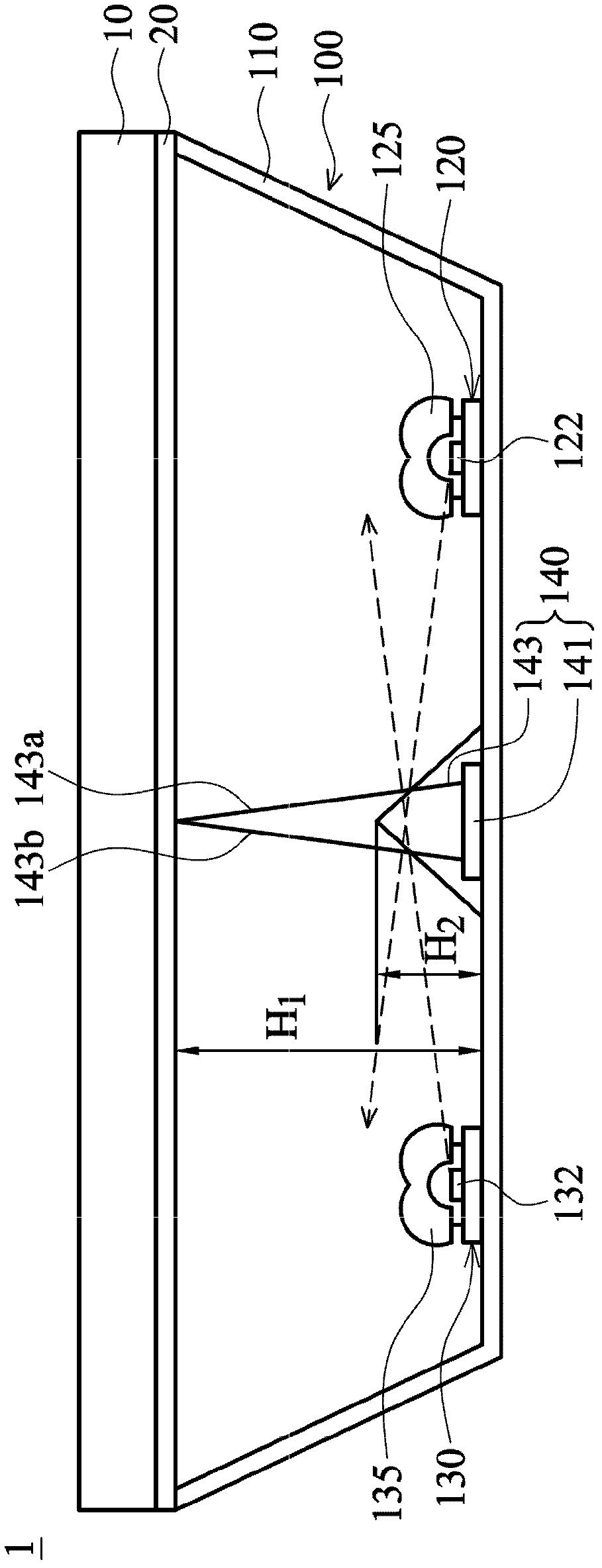
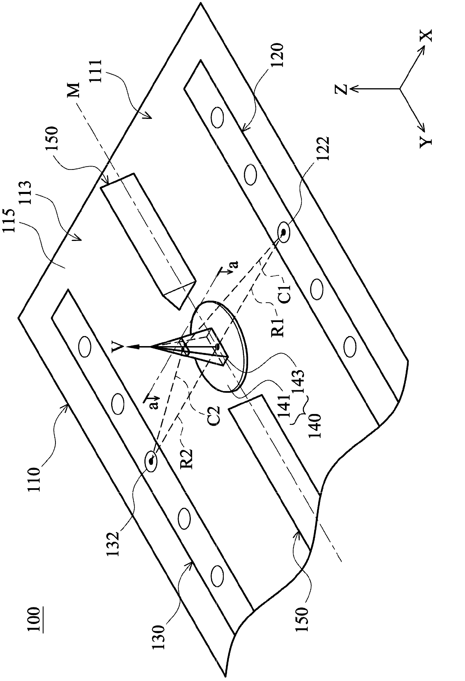
[0108] Please refer to figure 2 . figure 2 A display device 1 of a preferred embodiment of the present invention is shown. The display device 1 includes a display panel 10 , an optical film 20 , and a backlight module 100 . The display panel 10 is disposed on the backlight module 100 , and the optical film 20 is disposed between the display panel 10 and the backlight module 100 . The backlight module 100 includes a substrate 110 , a first light bar 120 , a second light bar 130 , at least one polygonal support 140 and a plurality of spacers 150 , wherein the optical film 20 is disposed on the polygonal support 140 .

[0109] Please refer to image 3 , Figure 4 . image 3 A schematic diagram showing some components of the backlight module 100 according to the first embodiment of the present invention, Figure 4 show image 3 The sectional view along the section line a-a i...


PUM


Abstract

The invention provides a backlight module which comprises a substrate, a light source and at least one polygonal supporting piece, wherein the substrate comprises a bottom surface, and the light source is arranged on the substrate. A cross section of the polygonal supporting piece comprises a first side edge, and an included angle between a projection line of a connecting line of a middle point of the first side edge and the light source on the bottom surface and a projection line of the first side edge on the bottom surface is in a range from 80 degrees to 100 degrees.

Description

technical field [0001] The invention relates to a backlight module, in particular to a backlight module with a support. Background technique [0002] With the rapid progress of liquid crystal display (liquid crystal display, LCD) production technology, and its advantages of lightness, lightness, power saving and no radiation, the liquid crystal display is widely used in tablet computers, notebook computers, digital cameras, digital cameras, etc. VCRs, mobile phones, computer screens and LCD TVs and other electronic products. However, since the liquid crystal display panel in the liquid crystal display is a non-self-illuminating display panel, it needs the light source provided by the backlight module to produce the display function. [0003] Large-sized liquid crystal display panels usually need to install several support members between the backlight module and the liquid crystal panel or between the backlight module and an optical plate such as a diffuser plate to maintai...

Claims


Application Information

Patent Timeline
IPC IPC(8): F21S8/00F21V21/00G02F1/13357
Inventor 张轩维黄士展叶政玮
Owner INNOCOM TECH SHENZHEN
Why Eureka
Try Eureka