Mechanical inertia identification method and device, and motor speed regulation system

A technology of mechanical inertia and identification method, which is applied in the electrical field and can solve problems such as difficult identification of mechanical inertia

Inactive Publication Date: 2013-07-31
HUAWEI TECH CO LTD
View PDF6 Cites 5 Cited by
  • Summary
  • Abstract
  • Description
  • Claims
  • Application Information

AI Technical Summary

Problems solved by technology

[0007] Embodiments of the present invention provide a mechanical inertia identification method, device, and motor speed control system to solve the p

Method used


Image

  • Mechanical inertia identification method and device, and motor speed regulation system
  • Mechanical inertia identification method and device, and motor speed regulation system
  • Mechanical inertia identification method and device, and motor speed regulation system

Examples


Embodiment 1

[0060] figure 1 It is a flow chart of Embodiment 1 of the mechanical inertia identification method of the present invention. The method is applicable to the mechanical inertia identification of various motor speed control systems, such as synchronous motor frequency conversion control systems, general frequency converter control systems, servo control systems, etc. Identification of mechanical inertia. The method can be implemented by a mechanical inertia identification device, and the mechanical inertia identification device can be a frequency converter or be integrated in a frequency converter, but not limited thereto. like figure 1 As shown, the method may include:

[0061] S101. The mechanical inertia identification device separately collects the electrical parameters of the motor during at least two time intervals during the motor's working with load, and calculates the torque and rotational speed of the motor, wherein at least one time interval includes at least one va...

Embodiment 2

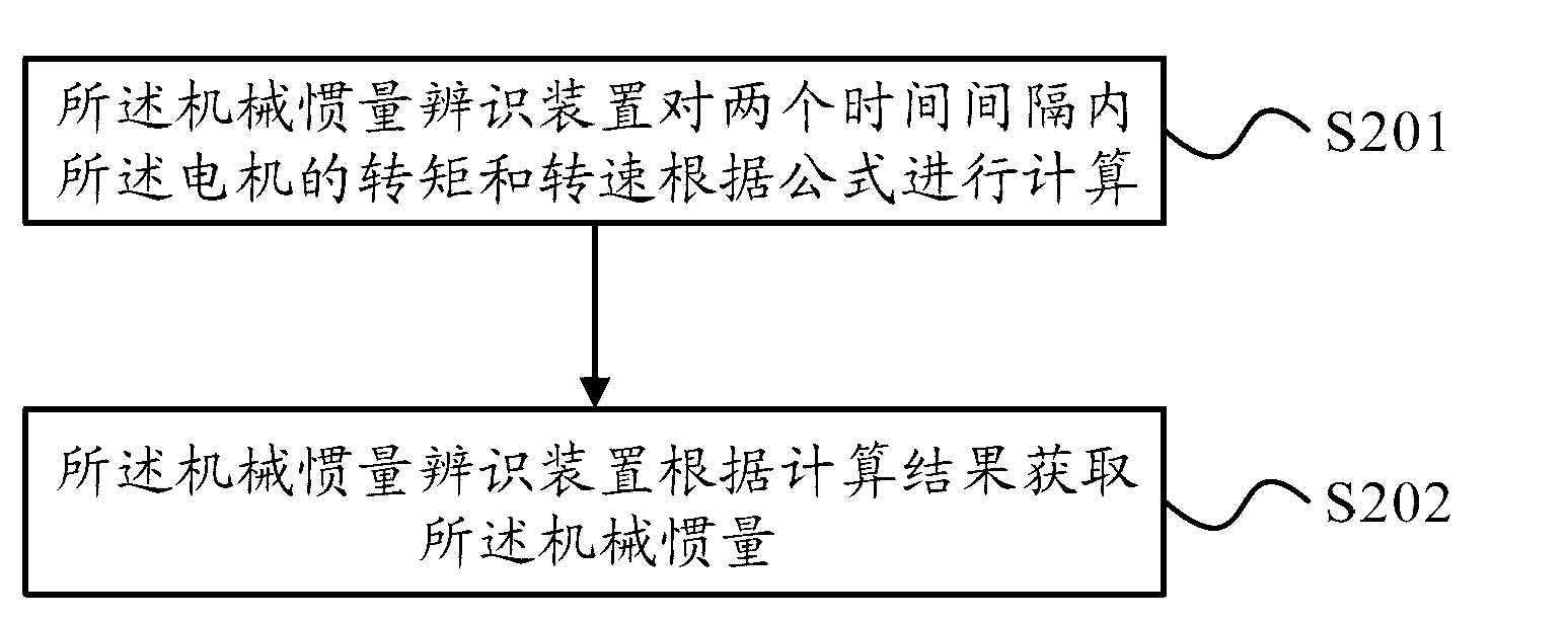
[0081] figure 2 It is a flow chart of Embodiment 2 of the mechanical inertia identification method of the present invention. In this embodiment, on the basis of the above-mentioned embodiments, the mechanical inertia identification device calculates out of the mechanical inertia, as figure 2 As shown, it can be done as follows:

[0082] S201. The mechanical inertia identification device calculates the torque and rotational speed of the motor within two time intervals according to a formula.

[0083] Specifically, the formula is:

[0084] J = nt cy Σ i = 1 m T emx ( i ) t cx - ...

Embodiment 3

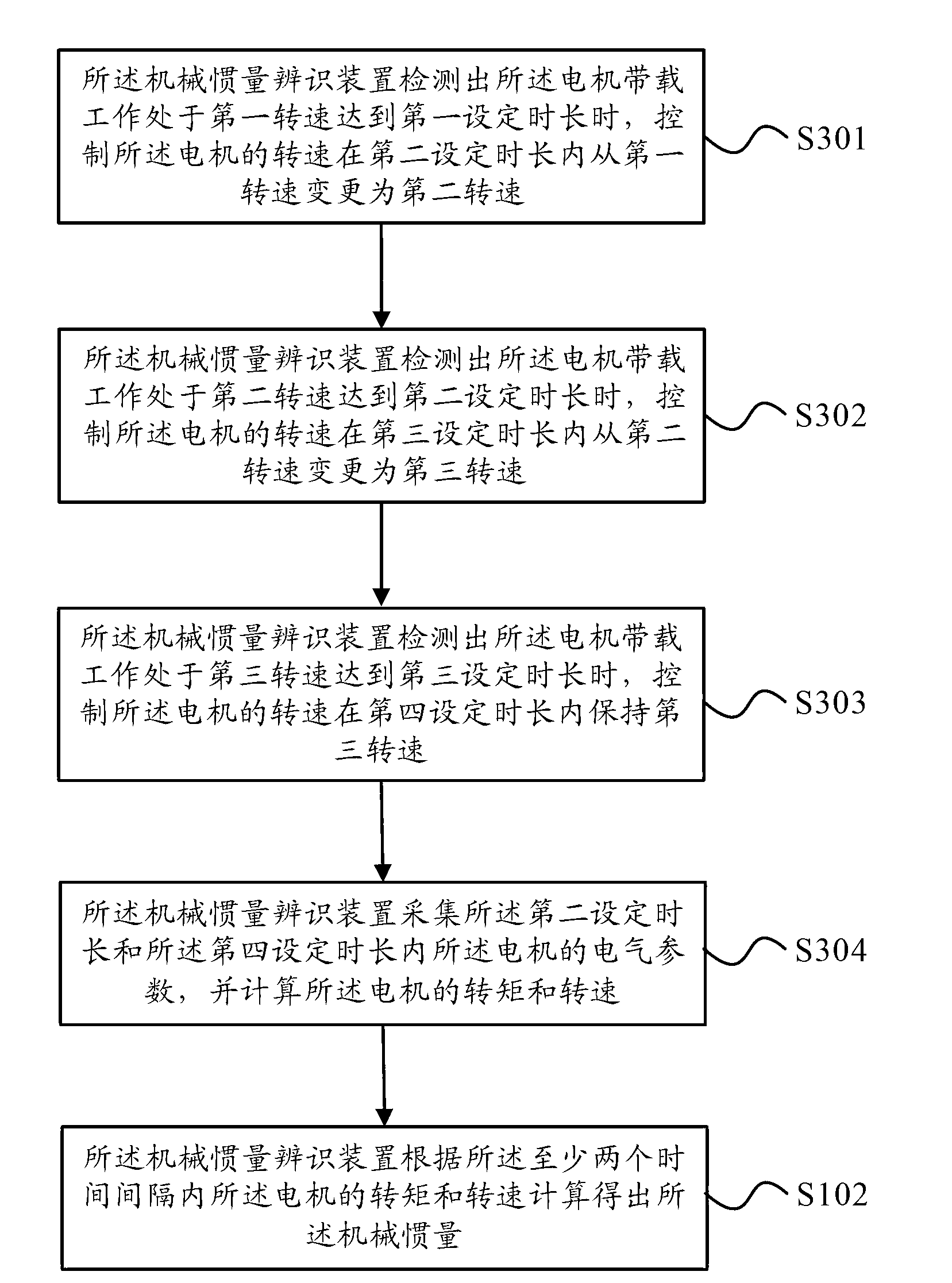
[0107] image 3 It is the flow chart of the third embodiment of the mechanical inertia identification method of the present invention. In this embodiment, on the basis of the above-mentioned embodiments, the mechanical inertia identification device collects the electrical parameters of the motor in at least two time intervals during the motor's working process with load. parameters, and calculate the torque and rotational speed of the motor, including: when the mechanical inertia identification device detects that the motor is operating under load at the first rotational speed and reaches the first set time, controlling the rotational speed of the motor at the second Change from the first rotational speed to the second rotational speed within the set duration; when the mechanical inertia identification device detects that the motor is operating with load at the second rotational speed and reaches the second set duration, it controls the rotational speed of the motor at the thir...


PUM


Abstract

The embodiment of the invention provides a mechanical inertia identification method and device, and a motor speed regulation system. The mechanical inertia identification method comprises the following steps: the mechanical inertia identification device collects electrical parameters of a motor respectively during at least two time intervals in the motor load working process, and calculates torques and rotating speeds of the motor, wherein at least one time interval comprises at least one speed changed working time range; and the mechanical inertia identification device calculates to obtain the mechanical inertia according to the torques and rotating speeds of the motor during the at least two time intervals. According to the embodiment of the invention, as the rotating speeds and torques of the motor are calculated through collecting the electrical parameters of the motor during the at least two time intervals, and the rotating speeds and torques of the motor are utilized to obtain the mechanical inertia, the mechanical inertia can be identified under smaller amount of calculation, and the problem of difficulty for identification of the mechanical inertia is solved.

Description

technical field [0001] Embodiments of the present invention relate to electrical technology, and in particular to a method and device for identifying mechanical inertia, and a motor speed regulating system. Background technique [0002] With the development of modern industry, motor speed control system has been developed rapidly and widely used. At the same time, higher requirements are put forward for the speed response and torque response of the motor speed control system. [0003] The mechanical inertia is the moment of inertia of the mechanical device connected to the load and the motor, and is an important reference parameter for the speed control of the motor speed control system. Since mechanical inertia is a parameter that cannot be directly measured, how to identify mechanical inertia becomes extremely important. At present, there are many methods of mechanical inertia identification, such as reference model adaptive method, Kalman filter method and least squares...

Claims


Application Information

Patent Timeline
IPC IPC(8): H02P29/00H02P21/14
Inventor 李剑飞王荣亮蔡畅
Owner HUAWEI TECH CO LTD
Why Eureka
Try Eureka