
Micro-mixing detecting chip

A detection chip and micro-mixing technology, which is applied in mixers, color/spectral characteristic measurement, dissolution, etc., can solve the problems of increasing costs, flow dead angles, unfavorable micro-channel flushing and reuse, and increasing the difficulty of micro-channel processing. Achieve the effects of low cost, improved mixing reaction efficiency, and fast and efficient mixed detection

Active Publication Date: 2015-03-25
INST OF ELECTRICAL ENG CHINESE ACAD OF SCI
View PDF6 Cites 0 Cited by
  • Summary
  • Abstract
  • Description
  • Claims
  • Application Information

AI Technical Summary

Problems solved by technology

The disadvantage is that it increases the difficulty of micro-channel processing, increases the cost, and the generation of flow dead ends is not conducive to the flushing and reuse of micro-channels.

Method used


Image

  • Micro-mixing detecting chip
  • Micro-mixing detecting chip
  • Micro-mixing detecting chip

Examples


Embodiment Construction

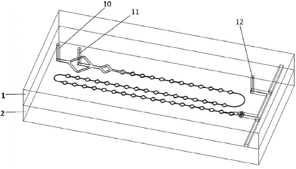
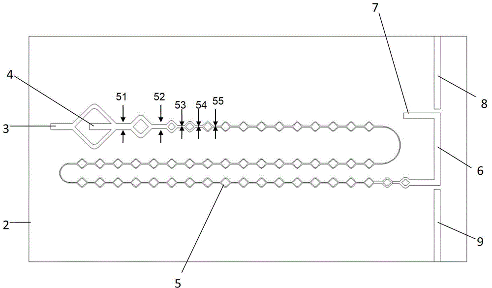
[0018] Such as figure 1 with figure 2 As shown, the embodiment of the micro-mix detection chip of the present invention has two inlets 3, 4 and one outlet 7, and two optical fiber channels 8, 9. This embodiment includes: a cover sheet 1 , a substrate 2 , inlets 3 and 4 , an outlet 7 , a detection channel 6 , optical fiber channels 8 and 9 , and a mixing channel 5 . The first inlet 3 is located at the front end of the second inlet 4, and the two inlets are located on the same straight line and communicate with the mixing channel. The mixing channel at the first inlet 3 is divided into two branches, which merge into the main mixing channel from both sides of the second inlet 4 . The two inlets 3 and 4 communicate with one end of the mixing channel 5, and the liquid A flowing in from the first inlet 3 is divided into two branches after the first inlet 3 flows in, and merges into the trunk of the mixing channel on both sides of the second inlet 4 , mixed with liquid B flowing ...


PUM

PropertyMeasurementUnit
widthaaaaaaaaaa
lengthaaaaaaaaaa
depthaaaaaaaaaa

Abstract

A micro-mixing detecting chip includes: m inlets, one outlet, a mixing channel (5), a detecting channel (6), two optical fiber channels (8,9), a substrate (2) and a cover plate (1). The mixing channel (5) is connected with the detecting channel (6), and the two optical fiber channels (8,9) are positioned on both sides of the detecting channel (6). The mixing channel (5), the detecting channel (6) and the optical fiber channels (8,9) are all etched on the substrate (2). The cover plate (1) is bonded to the substrate (2), and the cover plate (1) is provided with m input holes and one output hole which are respectively communicated with the m inlets and the one outlet on the substrate. The two optical fiber channels are respectively an incidence optical fiber channel for the insertion of an incidence optical fiber, and a receiving optical fiber channel for the insertion of a receiving optical fiber. The centerlines of the incidence optical fiber channel, the receiving optical fiber channel and the detecting channel are positioned on the same line and are not communicated with each other. The micro-mixing detecting chip of the present invention can be applied to an on-line trace detection system for continuously monitoring dynamic changes of required indicators.

Description

technical field [0001] The invention relates to a microfluidic chip, in particular to a micro-mixing chip integrating liquid mixing and detection. Background technique [0002] With the development of microfluidic chip technology, various micro-hybrid chips are widely used in analytical chemistry, biology, medical diagnosis, environmental monitoring and other fields. Microfluidic chips are simple to manufacture, low in cost, and the micron-level size reduces the consumption of samples, making them the first choice for various online micro-detection. The fluid mixing process can be divided into laminar flow mixing and turbulent flow mixing. In the micro-hybrid chip, because the characteristic scale of the channel is at the micron level, the Reynolds number is far less than 2000, the flow is mostly laminar, and the mixing efficiency is not high. Currently, active or passive methods are mainly used to improve the mixing effect. Active mixing uses external forces, such as mag...

Claims


Application Information

Patent Timeline
Patent Type & Authority Patents(China)
IPC IPC(8): B01F13/00G01N21/31
Inventor 曹越霍小林吴昌哲张广浩
Owner INST OF ELECTRICAL ENG CHINESE ACAD OF SCI
Learn More