Supercharge Your Innovation With Domain-Expert AI Agents!

Correlation interferometer direction-finding method based on phase difference increment

A related interferometer and phase difference technology, applied in the field of related interferometers, can solve the problems of phase blur, high hardware platform requirements, sacrificing direction finding accuracy, etc., and achieve the effect of high precision direction finding

Inactive Publication Date: 2013-08-07
UNIV OF ELECTRONIC SCI & TECH OF CHINA
View PDF9 Cites 24 Cited by
  • Summary
  • Abstract
  • Description
  • Claims
  • Application Information

AI Technical Summary

Problems solved by technology

These methods can ensure real-time direction finding by reducing the amount of system computation or increasing the processing speed, but they all have some shortcomings
Although the space angle direction finding method reduces the amount of calculation of the system, it sacrifices the direction finding accuracy; the GPU implementation can improve the processing speed through efficient parallel operations, but it has high requirements for the hardware platform; the direction finding method based on dimension splitting is in the While greatly reducing the amount of calculations, it can guarantee a high amount of calculations, but this method is due to the existence of phase ambiguity (see literature: Research on Angle of Arrival Estimation Method Based on Multi-group Deambiguation of Phase Interferometer Array, Gong Xiangyi, Yuan Junquan, Su Linghua; Journal of Electronics and Information Technology, 2006, 28 (1): Page (s): 55-59), it is difficult to apply to wide frequency range direction finding

Method used


Image

  • Correlation interferometer direction-finding method based on phase difference increment
  • Correlation interferometer direction-finding method based on phase difference increment
  • Correlation interferometer direction-finding method based on phase difference increment

Examples


Embodiment Construction

[0033] The present invention will be further described in detail below in conjunction with the drawings and embodiments.

[0034] For the convenience of the following description, first define the following:

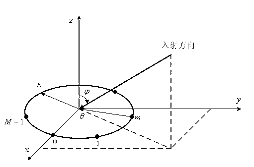
[0035] Correlation interferometer: Correlation interferometer is a kind of measurement by calculating the similarity between the actual measured vector and the vector samples in the existing sample library, and selecting the signal arrival direction corresponding to the sample with the highest similarity in the sample library as the incident direction. To equipment.

[0036] Phase difference sample library: The phase difference sample library is an orderly arrangement of the phase difference vectors measured by the system at each discrete incident frequency, incident azimuth angle, and incident elevation angle before the actual incident angle measurement. Vector library.

[0037] Phase difference increment (Δφ i ): The phase difference increment is the change value of the same ...


PUM


Abstract

The invention relates to the field of correlation interferometers in radar, and discloses a correlation interferometer direction-finding method based on phase difference increment. The method includes step 1, confirming azimuthal angle increment; step 2, acquiring an actually measured phase difference incremental vector; step 3, acquiring a non-fuzzy actually measured phase difference incremental vector; step 4, selecting all the phase difference incremental vector samples with pitch angles as fixed angles; step 5, calculating similarities of the actually measured phase difference incremental vector and selected phase difference incremental vector samples selected in the step 4; step 6, acquiring an azimuthal angle rough estimated value; step 7, selecting all the phase difference incremental vector samples with azimuthal angles same as the azimuthal angle rough estimated value in step 6; step 8, calculating similarities of the actually measured phase difference incremental vector and the selected phase difference incremental vector samples in step 7; step 9, acquiring a pitch angle rough estimated value and an azimuthal angle rough estimated value; step 10, forming a new sample database; and step 11, calculating similarities to acquire an pitch angle estimated value and an azimuthal angle estimated value. With the correlation interferometer direction-finding method, rapid and high-precision direction finding of the direction-finding system can be realized within wide frequency range.

Description

Technical field [0001] The invention belongs to the field of correlation interferometers in radar communication, and in particular relates to a direction finding method of correlation interferometers based on phase difference increments. Background technique [0002] In the existing direction finding system, interferometer direction finding has the advantages of high direction finding accuracy, simple method, and fast speed, so it has been widely used in military and civilian fields. In the military field, it can locate radiation sources such as radar, communication, measurement and control, and can play an important role in the implementation of targeted electronic interference and military strikes; in the civilian field, it can be used for traffic control, life rescue, and radio spectrum management. etc. [0003] The phase interferometer determines the direction of the incoming wave signal by measuring the phase difference between the receiving elements. In various phase interfe...

Claims


Application Information

Patent Timeline
IPC IPC(8): G01S3/00
Inventor 桂新涛程婷何子述
Owner UNIV OF ELECTRONIC SCI & TECH OF CHINA
Features
  • R&D
  • Intellectual Property
  • Life Sciences
  • Materials
  • Tech Scout
  • Unparalleled Data Quality
  • Higher Quality Content
  • 60% Fewer Hallucinations
Learn More