Antenna with multiple signal feed ports

A multi-signal, port technology, applied in antenna coupling and other directions, can solve the problems of poor antenna isolation, inability to improve antenna isolation, and increasingly high isolation requirements

Active Publication Date: 2013-08-07
COMBA TELECOM TECH (GUANGZHOU) CO LTD
View PDF10 Cites 9 Cited by
  • Summary
  • Abstract
  • Description
  • Claims
  • Application Information

AI Technical Summary

Problems solved by technology

In the known prior art of the pieces listed above, the positions of the decoupling components are fixed once they are installed. The applicant found that the decoupling components at the same position are relatively There are great differences in the adjustment of the isolation of the antenna. For example, at a specific electrical downtilt, the decoupling component at a specific position can improve the isolation of the antenna, but when the electrical downtilt changes, the decoupling at this position The role of the coupling components is also changing. The decoupling components in some positions not only fail to improve the isolation of the antenna, but also make the isolation of the antenna worse. Therefore, it brings great difficulties to the adjustment of the isolation of the multi-polarized antenna.
Especially as the electrical downtilt range of multi-frequency shared antennas becomes wider and wider (for example, the continuous downtilt range of 15dBi gain range antenna is 0-30°), the antenna isolation becomes larger and larger with the electrical downtilt angle, and the network In order to improve the network quality, operators have higher and higher requirements on the isolation between the input ports of each array antenna, which makes it very difficult to achieve the isolation index of multi-polarized antennas
Therefore, in this context, how to improve the isolation between the input ports of each array antenna poses a certain challenge to those skilled in the art

Method used


Image

  • Antenna with multiple signal feed ports
  • Antenna with multiple signal feed ports
  • Antenna with multiple signal feed ports

Examples


Embodiment Construction

[0026] Embodiments of the present invention will be described in detail below in conjunction with the accompanying drawings.

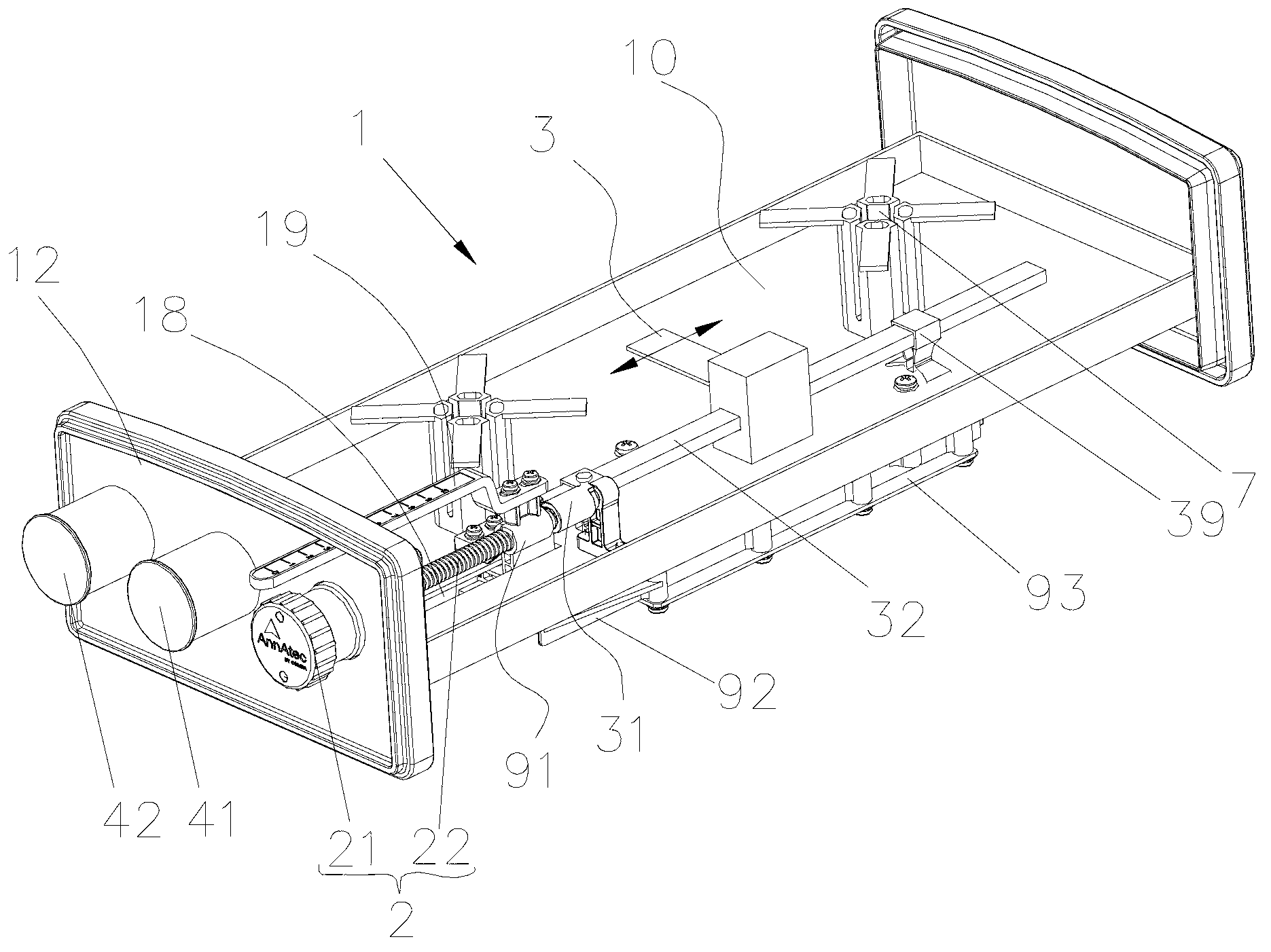
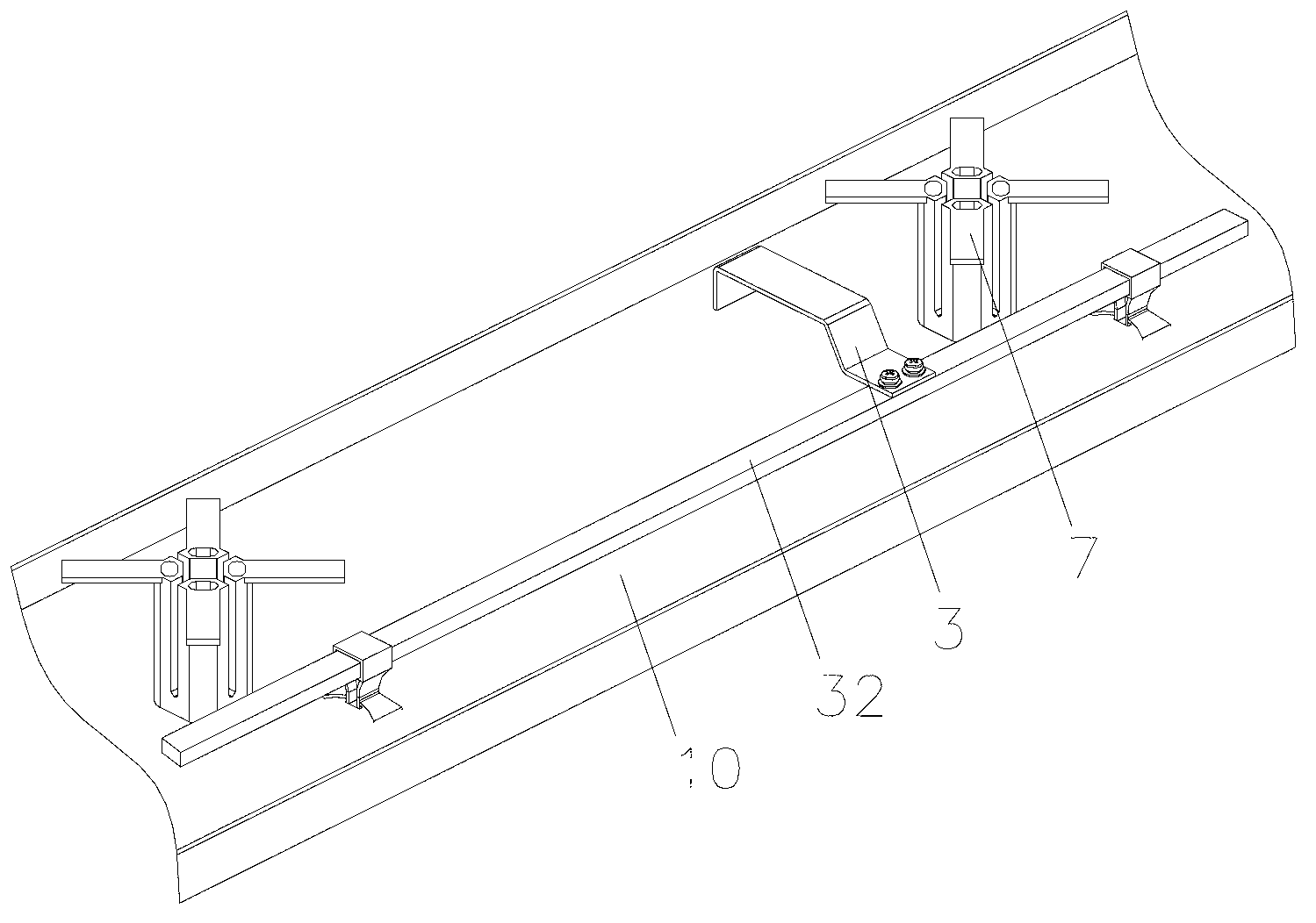
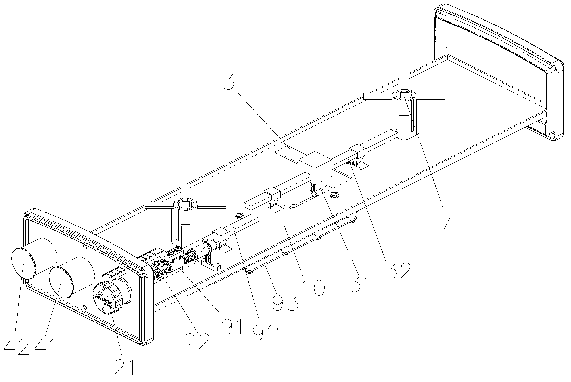
[0027] see figure 1 The shown concrete structure of the present invention has the first embodiment of the antenna of multi-signal feed-in port, and this structure shows a planar antenna 1, and this antenna 1 has a metal reflector 10 that is elongated shape, and the metal reflector Both ends of the longitudinal direction of 10 are respectively connected to a cover plate 12, and on the metal reflector 10, a plurality of dual-polarized radiation units are arranged at intervals along the longitudinal direction to form a radiation unit column 7. Obviously, the antenna 1 disclosed in this embodiment It is a traditional dual-polarized antenna 1. Although two radiating elements are used as an example, those skilled in the art should know that the number of 7 radiating elements on the antenna 1 depends on the actual application situation, and the number should ...


PUM


Abstract

The invention discloses an antenna with multiple signal feed ports. The antenna comprises a plurality of radiation units, at least one phase shifting device and at last one decoupling unit; the radiation units are assembled in physical space, the phase shifting devices are used for changing phases of signals which are fed to the radiation units of the antenna so as to change tilt and elevation angles of beams of the antenna, the decoupling units are used for reducing coupling of electromagnetic fields among the various feed ports, and each phase shifting device is provided with an adjusting component, so that a plurality of phase shifters can be controlled to shift the phases synchronously; and torque of each adjusting component is transmitted to the corresponding decoupling unit, so that direction change of the decoupling units and phase shifting operation of the various phase shifters are synchronized. The antenna has the advantages that the decoupling units are restrained to synchronously move along with phase shifting movement for adjusting the phases of the signals of the antenna, so that adjustment for coupling of the electromagnetic fields among the feed ports of the antenna is related to the tilt and elevation angles of the beams of the antenna, and the isolation of the antenna is changed while the phases of the signals of the antenna are adjusted to change the tilt and elevation angles of the beams.

Description

【Technical field】 [0001] The invention relates to an antenna suitable for a mobile communication system, in particular to an antenna with multiple signal feed-in ports. 【Background technique】 [0002] The currently known multi-polarization antenna isolation adjustment method is typically characterized by the fact that the position of the decoupling component used to adjust the signal isolation between the radiating elements is fixed and cannot be moved. Even if the tilt angle of the antenna beam is adjusted, the position of the decoupling component remains the same. Fixed, please refer to patent announcement No. US6734829B1, patent announcement No. CN100435413C, and patent announcement No. US006072439A. In the known prior art of the pieces listed above, the positions of the decoupling components are fixed once they are installed. The applicant found that the decoupling components at the same position are relatively There are great differences in the adjustment of the isolat...

Claims


Application Information

Patent Timeline
Patent Type & Authority Applications(China)
IPC IPC(8): H01Q1/52
Inventor 刘培涛王强
Owner COMBA TELECOM TECH (GUANGZHOU) CO LTD
Why Eureka
Try Eureka