Devices and techniques for cutting and coagulating tissue
A generator, frequency technology, applied in the field of ultrasound systems, which can solve problems such as limited capacity and patient exposure
- Summary
- Abstract
- Description
- Claims
- Application Information
AI Technical Summary
Problems solved by technology
Method used
Image
Examples
example 1
[0261] Example 1: Monitoring Frequency Slope Against Corresponding Thresholds
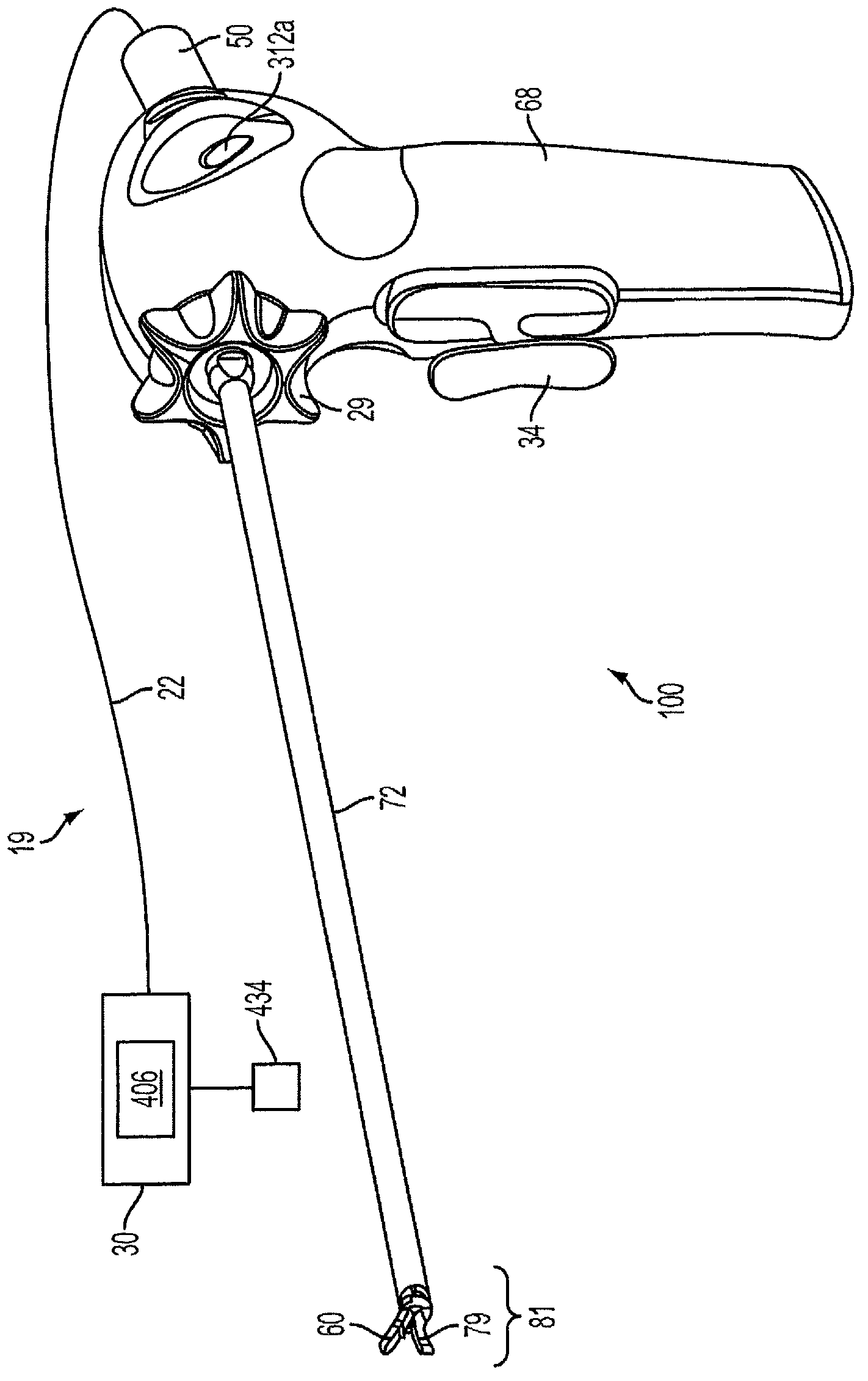
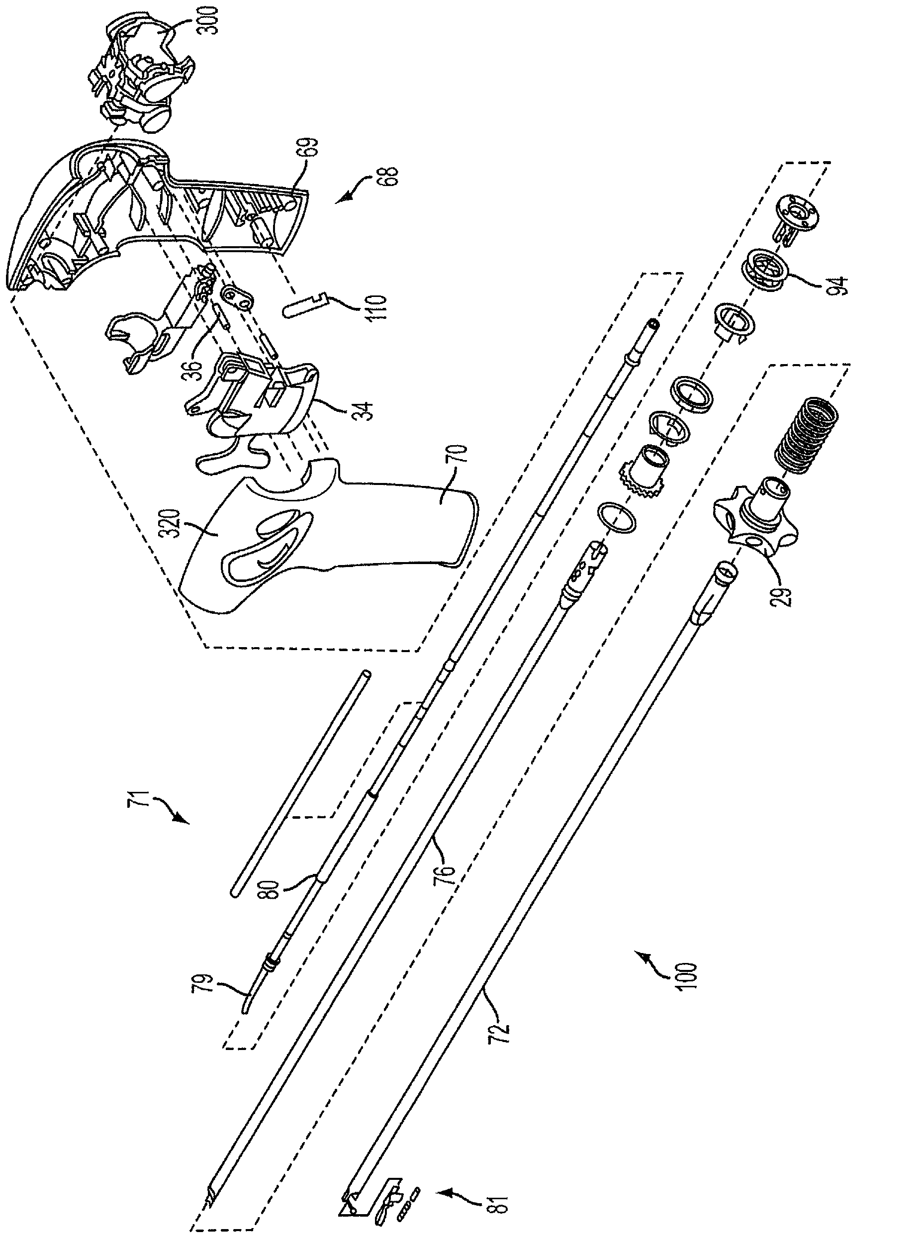
[0262]A first example scenario involves monitoring frequency slopes against respective thresholds and is shown in conjunction with FIGS. 23-28 . The simplest first example is one that triggers a set of responses based only on the frequency slope. Table 4 contains representative parameters for this purpose for a surgical instrument such as any of the surgical instruments 19, 190, 1000 disclosed herein including corresponding ultrasonic instruments (e.g., ultrasonic instruments 100, 120, 1004 disclosed herein). one.
[0263] Table 4: For triggering auditory indications based only on frequency slope thresholds (using a condition set) The representative parameters shown
[0264]
[0265] *These parameter values are set to suitably extreme values so that they don't effectively participate in the logic flow (eg, set to always be "true").
[0266] Figures 23-25 show the signal data produce...
example 2
[0276] Example 2: Triggering Response Collections Based Only on Frequency Thresholds
[0277] refer to Figure 29-35 , a second example scenario includes triggering a response set based only on a frequency threshold. Table 5 contains representative parameters for this purpose in conjunction with a surgical instrument, such as any of the surgical instruments 19, 190, 1000 disclosed herein including corresponding ultrasonic instruments (e.g., ultrasonic instruments 100, 120, 1004 disclosed herein). By. It should be understood that the usefulness of triggering via frequency thresholds may be limited due to the low characterization of dynamic end effector states, and is presented herein for the completeness of the disclosure. The inclusion of frequency slope in the tissue algorithms described in connection with logic flow diagrams 1200, 1300, 1400 is intended to be used in conjunction with the logic discussed in the next section of this specification (in conjunction with the u...
example 3
[0293] Example 3: Triggering Response Sets Based on Both Frequency Slope Threshold and Frequency Threshold
[0294] A third example scenario includes triggering a response set based on both the frequency slope threshold and the frequency threshold. Table 6 contains representative parameters for this purpose in conjunction with a surgical instrument, such as any of the surgical instruments 19, 190, 1000 disclosed herein including corresponding ultrasonic instruments (e.g., ultrasonic instruments 100, 120, 1004 disclosed herein). By.
[0295] Table 6: For triggering by frequency slope threshold and frequency threshold (using two condition sets) Representative parameters for auditory indications
[0296]
[0297]
[0298] * These parameter values are set to suitably extreme values so that they don't effectively participate in the logic flow (e.g. set to always be "true")
[0299] In this case of Example 3, a stratified or layered response was exhibited. will us...
PUM
 Abstract
Description
Claims
Application Information
 - R&D
- Intellectual Property
- Life Sciences
- Materials
- Tech Scout
- Unparalleled Data Quality
- Higher Quality Content
- 60% Fewer Hallucinations
Browse by: Latest US Patents, China's latest patents, Technical Efficacy Thesaurus, Application Domain, Technology Topic, Popular Technical Reports.
© 2025 PatSnap. All rights reserved.Legal|Privacy policy|Modern Slavery Act Transparency Statement|Sitemap|About US| Contact US: help@patsnap.com


