Vehicle motion control apparatus, and vehicle motion control method

A motion control device and motion control technology, applied in the direction of power devices, brake control systems, automatic starting devices, etc., can solve the problems of reduced responsiveness, increase regenerative braking force or electric driving force, and improve driving stability Effect

Inactive Publication Date: 2013-08-14
HITACHI AUTOMOTIVE SYST LTD
View PDF9 Cites 34 Cited by
  • Summary
  • Abstract
  • Description
  • Claims
  • Application Information

AI Technical Summary

Problems solved by technology

[0007] However, in the brake control device disclosed in Patent Document 1, the slip ratio is used as an index to determine control intervention. For example, when the friction coefficient between the road surface and the wheels is low, there may be make it less responsive
For example, in order to improve responsiveness when the friction coefficient between the road surface and the wheels is low, it is conceivable to set the control intervention threshold of the slip ratio to be extremely small, but if the control intervention threshold of the slip ratio If it is set to a small value, the slip ratio can be easily adjusted regardless of whether the grip force of the wheel (the degree of adhesion between the road surface and the tire) has a margin when the friction coefficient between the road surface and the wheel is high. If the control intervention threshold is exceeded, there is a problem that the regeneration amount of the regenerative braking unit will be suppressed more than necessary

Method used


Image

  • Vehicle motion control apparatus, and vehicle motion control method
  • Vehicle motion control apparatus, and vehicle motion control method
  • Vehicle motion control apparatus, and vehicle motion control method

Examples


Embodiment Construction

[0044] Hereinafter, embodiments of a vehicle motion control device and a vehicle motion control method according to the present invention will be described with reference to the drawings.

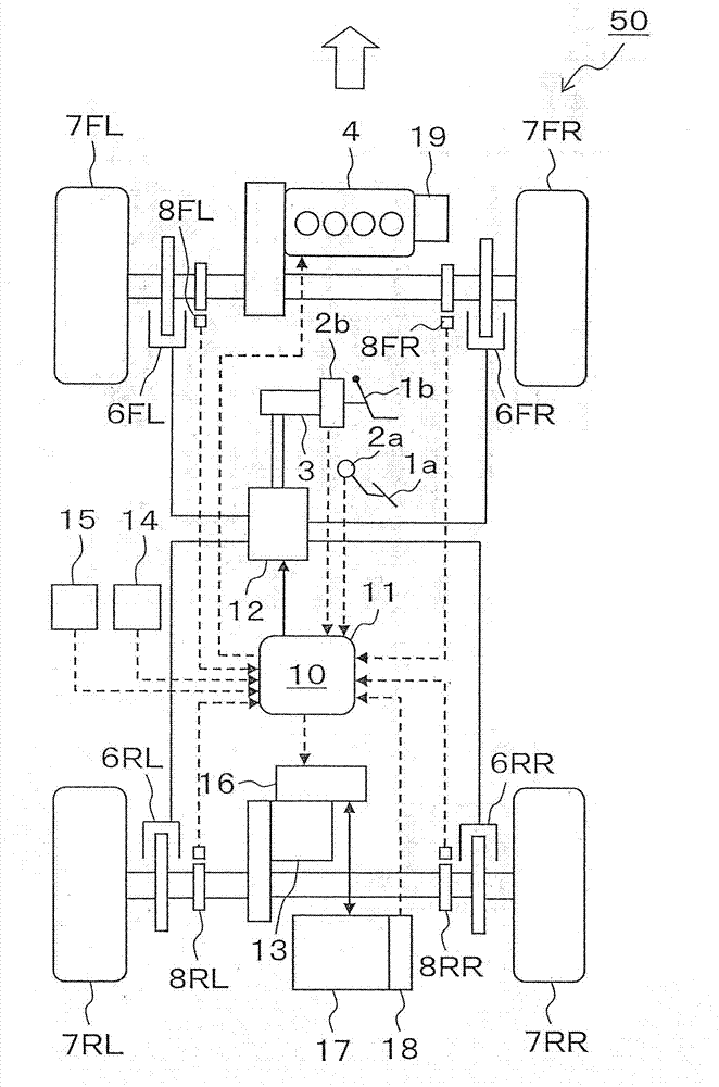
[0045] figure 1 A basic configuration of a vehicle 50 to which the vehicle motion control device 10 according to the present invention is applied is shown.

[0046] The vehicle 50 includes left and right front wheels 7FL, 7FR and left and right rear wheels 7RL, 7RR at its front and rear.

[0047] An engine (drive source) 4 is mechanically connected to the front wheels 7FL, 7FR of the vehicle 50 , and the engine 4 generates a driving force for propelling the vehicle 50 to the front wheels 7FL, 7FR.

[0048] In addition, an electric motor 13 is mechanically connected to the rear wheels 7RL, 7RR of the vehicle 50 , and the electric motor 13 causes the rear wheels 7RL, 7RR to generate a braking driving force of the vehicle 50 . In addition, the braking and driving force may include at least o...


PUM


Abstract

A vehicle motion control apparatus that the travel stability of a vehicle can be maintained by appropriately controlling the regenerative braking force in accordance with the wheel slip state or the road surface friction coefficient, and that the amount of regeneration of regenerative energy by the electric motor can be ensured under various situations which may range from gradual braking to rapid braking is provided. A braking / driving force allocation unit of the vehicle motion control apparatus allocates braking / driving force to a front wheel and a rear wheel on the basis of braking / driving force required for the vehicle 50 and decreases the braking / driving force for one of the front wheel and the rear wheel for which the braking / driving force is generated by the electric motor 13 in response to a decrease in the ratio of braking / driving force to a slip ratio of at least one of the front wheel and the rear wheel.

Description

technical field [0001] The present invention relates to a vehicle motion control device and a vehicle motion control method, for example, to a control device and a control method for controlling the motion of a vehicle in which driving force is generated by an engine and a motor and braking force is generated by a friction brake and a motor. Background technique [0002] Conventionally, vehicles equipped with electric motors have combined friction braking, which converts kinetic energy of the vehicle into thermal energy to decelerate the vehicle through friction members provided on the wheels, and used electric motors to convert the kinetic energy of the vehicle into electrical energy in order to perform efficient braking control of the vehicle. Regenerative braking to slow the vehicle down. [0003] In the above-mentioned vehicle equipped with an electric motor, the amount of regeneration of kinetic energy of the vehicle can be effectively increased by generating more braki...

Claims


Application Information

Patent Timeline
Patent Type & Authority Applications(China)
IPC IPC(8): B60L7/18B60L7/24B60L50/16
CPCB60L7/18B60T13/662B60T13/585B60T17/221B60K6/52B60T1/10B60T7/042Y02T10/6265B60L7/26B60W30/18127Y10S903/947B60T8/1755B60T17/22B60W10/18B60W20/10B60T8/28B60T2270/613B60T8/175B60W10/192B60T8/1761B60T8/171B60W20/1062B60T8/1763B60W10/08B60T8/3255B60T8/26B60T7/22B60L3/102B60L3/108B60T8/267B60W20/14Y02T10/62
Inventor 横山笃大泽俊哉
Owner HITACHI AUTOMOTIVE SYST LTD
Why Eureka
Try Eureka