
Backlight module

A backlight module and backside technology, which is applied to the field of backlight modules with reflective sheets, can solve the problems of uneven structure of adhesive layer, affecting the light output effect of the backlight module, and bright halo of the light guide plate, so as to improve the light output effect and improve the brightness. halo effect

Inactive Publication Date: 2013-08-14
CORETRONIC
View PDF6 Cites 9 Cited by
  • Summary
  • Abstract
  • Description
  • Claims
  • Application Information

AI Technical Summary

Problems solved by technology

Gluing the reflective sheet to the side of the light guide plate through the adhesive layer is a common fixing method. However, due to the uneven internal structure of the adhesive layer, the light passing through the adhesive layer is scattered and other phenomena, resulting in bright halos on the light guide plate and affecting the backlight. The light effect of the module

Method used


Image

  • Backlight module
  • Backlight module
  • Backlight module

Examples

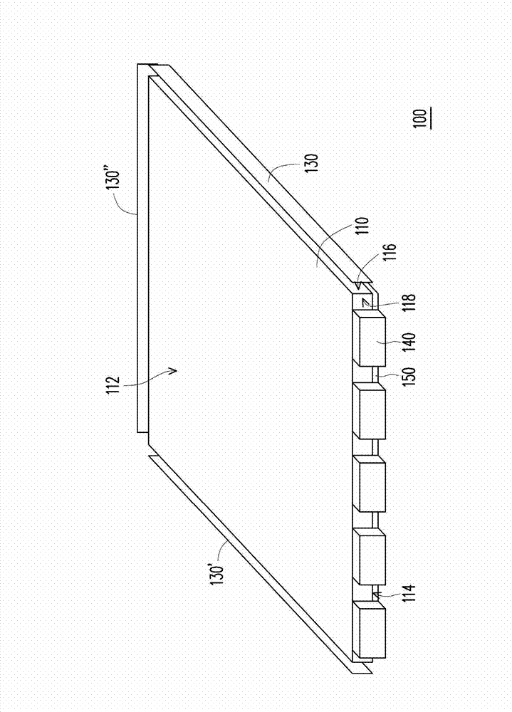
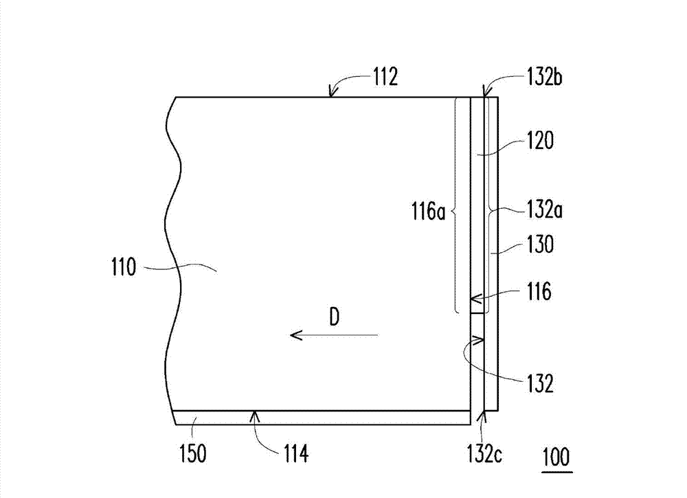

Embodiment Construction

[0026] The aforementioned and other technical contents, features and effects of the present invention will be clearly presented in the following detailed descriptions of multiple embodiments with accompanying drawings. The directional terms mentioned in the following embodiments, such as up, down, front, back, left, right, etc., are only directions referring to the drawings. Accordingly, the directional terms are used to illustrate, not to limit, the invention.

[0027] figure 1 It is a perspective view of a backlight module according to an embodiment of the present invention. figure 2 for figure 1 Partial cross-sectional view of the backlight module. image 3 for figure 1 The schematic diagram of the first reflection sheet and adhesive layer. Please refer to Figure 1 to Figure 3 The backlight module 100 of this embodiment includes a light guide plate 110 , an adhesive layer 120 , a first reflective sheet 130 and at least one light source 140 (a plurality is shown in t...


PUM


Abstract

A backlight module comprises a light guide plate, a glue layer, a first reflector plate and at least one light source. The light guide plate comprises an outgoing light surface, a backside, a first side surface and a second side surface. The outgoing light surface is relative to the backside, the first and second side surfaces are connected between the outgoing light surface and the backside separately, and the glue layer is adhered on the first side surface. The area of the region cover by the glue layer of the first side surface is less than three-fourth of the total area of the first side surface. The first reflector plate possesses a reflecting surface which is adhered on the glue layer to fix the first reflector plate on the first side surface, and the light source is arranged on the second side surface. The backlight module provided by the invention possesses a better outgoing light effect.

Description

technical field [0001] The present invention relates to a backlight module, and in particular to a backlight module with a reflection sheet. Background technique [0002] Current electronic devices mostly use flat panel display modules to display images, among which the technology of liquid crystal display modules is relatively sophisticated and popular. However, since the display panel of the liquid crystal display module itself cannot emit light, a backlight module is provided under the display panel to provide light required for displaying images. [0003] Generally speaking, a side-edge backlight module includes components such as a light source and a light guide plate. The main function of the light guide plate is to generate a uniform surface light source by conducting the line light source through a medium and energy divergence mechanism and modulation method. In addition, reflective sheets can be arranged on the back and side of the light guide plate, so that the li...

Claims


Application Information

Patent Timeline
Patent Type & Authority Applications(China)
IPC IPC(8): F21S8/00F21V17/10F21V13/12
Inventor 林锦明李启龙吴家钊
Owner CORETRONIC
Learn More