Well breaking point guided earthquake minor fault interpretation method and device

A technology of small faults and breakpoints, applied in seismology and seismic signal processing for logging records, etc., can solve problems such as time-consuming and laborious, increasing difficulty of interpretation of small faults, and heavy workload

Active Publication Date: 2013-08-14
PETROCHINA CO LTD
View PDF2 Cites 30 Cited by
  • Summary
  • Abstract
  • Description
  • Claims
  • Application Information

AI Technical Summary

Problems solved by technology

[0010] Changes in lithology, structure, and other factors, like the existence of small faults, can also bring about changes in the continuity, smoothness, and amplitude of seismic reflection events, making attributes such as seismic slices, coherent bodies, dip detection, and ant bodies Anomaly features do not necessarily indicate the existence of faults. Therefore, seismic technology has a certain degree of multi-solution in identifying small faults, which increases the difficulty of small fault interpretation.
[0011] 2. Conventional seismic technology is difficult to identify low-order small faults
Due to the high density of well pattern in high water-cut oilfields, usually hundreds of wells are needed in a working area of ​​several square kilometers. If the synthetic record method is used to carry out deep-time conversion, the synthetic record is produced one by one, and then manually calibrated with the actual seismic record. , the workload is very huge, time-consuming and labor-intensive, and there are often certain accuracy problems due to manual calibration

Method used


Image

  • Well breaking point guided earthquake minor fault interpretation method and device
  • Well breaking point guided earthquake minor fault interpretation method and device
  • Well breaking point guided earthquake minor fault interpretation method and device

Examples


Embodiment Construction

[0070] In order to make the purpose, technical solutions and advantages of the embodiments of the present invention more clear, the embodiments of the present invention will be further described in detail below in conjunction with the accompanying drawings. Here, the exemplary embodiments and descriptions of the present invention are used to explain the present invention, but not to limit the present invention.

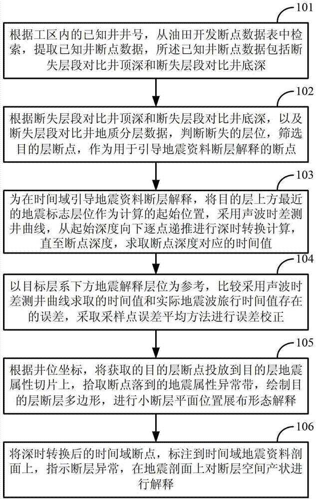
[0071]Faults play an important role in dividing the injection-production relationship between oil and water wells, and are important factors controlling oil and gas accumulation and distribution of remaining oil. It is very important and necessary to reconstruct the understanding system of underground faults in high water-cut oilfields, whether it is to carry out fine reservoir numerical simulation to predict the distribution of remaining oil, to improve the injection-production relationship, to prevent the fault loss of the target layer, or to deflect along the fault ...


PUM


Abstract

The invention discloses a well breaking point guided earthquake minor fault interpretation method and device. The method includes the following steps: extracting the known well breaking point data; screening a breaking point of a target stratum; obtaining the time value corresponding to the depth of the breaking point through an interval transit time well logging curve, and performing depth-to-time conversion; taking a seismic interpretation position under the target stratum as a reference, comparing the time value obtained through adopting the interval transit time well logging curve with the actual seismic wave travel time value, and correcting the depth-to-time conversion error of the breaking point through adopting the error averaging method of a sampling point; according to the coordinate of a well position, placing the obtained breaking point of the target stratum to a seismic attribution slice of the target stratum, picking up an abnormal seismic attribution zone where the breaking point falls on, mapping a fault polygon of the target stratum, and performing the distribution state interpretation of the plane position of the minor fault; and marking the time domain breaking point after the depth-to-time conversion to a section of the time domain seismic data to indicate that the fault is abnormal, and interpreting the space occurrence of the fault on the seismic section. The method and the device can be used for effectively reducing the multiple interpretation for interpreting the fault of seismic data.

Description

technical field [0001] The invention relates to the technical field of seismic data interpretation of high water-cut oilfields, in particular to a small seismic fault interpretation method and device guided by well interruption points. Background technique [0002] Faults are well developed in my country's onshore old oilfields, especially in the eastern Bohai Bay area, where the fault blocks are small and have great differences. The identification of large faults is relatively easy whether using well data or seismic data interpretation, but the identification of small faults is very difficult, especially in many old oilfields that have never done 3D seismic work, using early 2D seismic data and infill wells There is a certain accuracy problem in data interpretation and combination of faults. There are many breakpoints in well interpretation that are difficult to combine, and there may be some small faults between wells that have not been discovered. The production tests in...

Claims


Application Information

Patent Timeline
Patent Type & Authority Applications(China)
IPC IPC(8): G01V1/28G01V1/40
Inventor 刘文岭
Owner PETROCHINA CO LTD
Why Eureka
Try Eureka