
Electric connection terminal and assembly having the electric connection terminal

An electrical connection and terminal technology, applied in the field of components including the terminal, achieves the effects of reducing the quantity, reducing the price and cost, and having a simple installation method

Inactive Publication Date: 2013-08-14
ABB FRANS
View PDF3 Cites 2 Cited by
  • Summary
  • Abstract
  • Description
  • Claims
  • Application Information

AI Technical Summary

Problems solved by technology

[0012] However, the terminal 1 thus has many parts, and for reasons of simplification of installation and manufacturing costs, it is desirable to reduce the number of parts

Method used


Image

  • Electric connection terminal and assembly having the electric connection terminal
  • Electric connection terminal and assembly having the electric connection terminal
  • Electric connection terminal and assembly having the electric connection terminal

Examples


Embodiment Construction

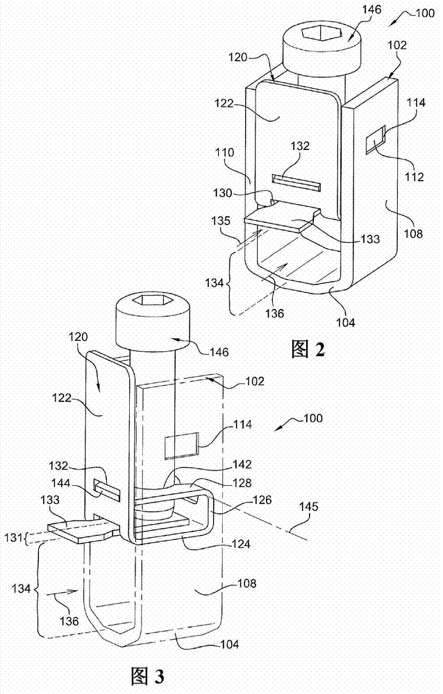
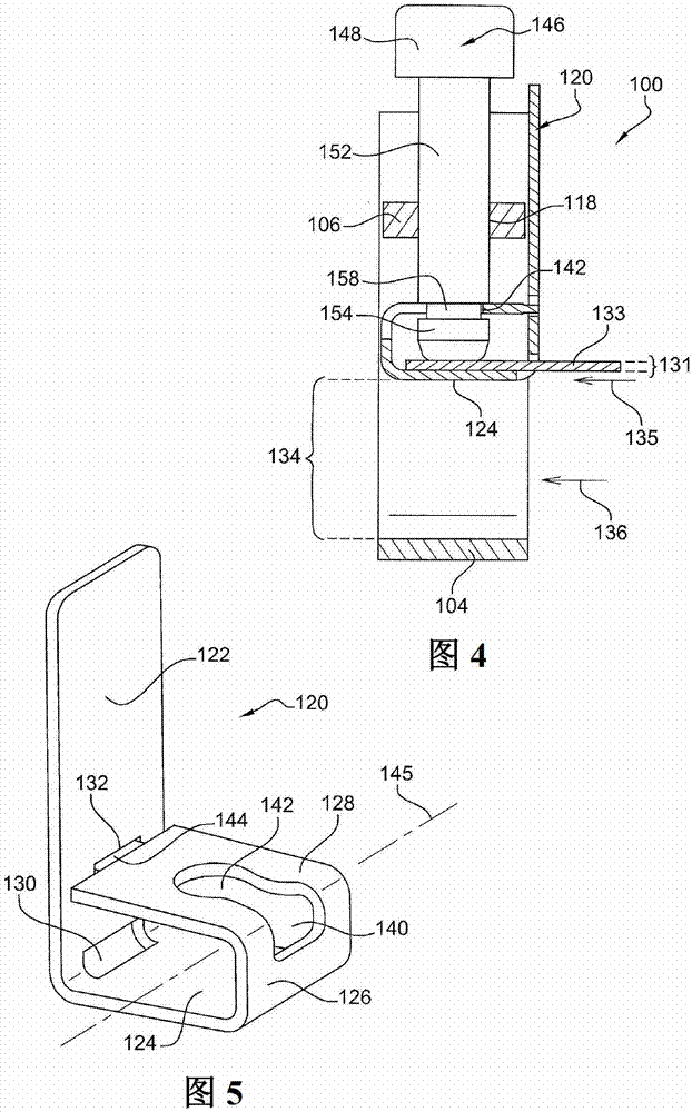
[0062] Figure 2 to 4 The electrical connection terminal 100 according to the present invention is shown. The terminal 100 includes a holder 102, which includes:

[0063] -Anti-support wall 104;

[0064] -The screw wall 106 opposite to the anti-support wall 104 (in Figure 4 Shown in); and

[0065] -Connect the counter-support wall 104 to the connecting walls 108 and 110 of the screwing wall 106.

[0066] The holder 102 is made by plastic deformation of a metal sheet, so the first part of the blade forms the connecting wall 108, the second part forms the counter-support wall 104, and the third part forms the connecting wall 110.

[0067] The screwing wall 106 is added and attached to the connecting walls 108 and 110. For this purpose, the screwing wall 106 includes two protrusions 112, and each of the connecting walls 108 and 110 includes a recess 114 into which a respective protrusion 112 is engaged.

[0068] The screwing wall 106 is provided with a threaded hole 118.

[0069] The term...


PUM


Abstract

The terminal (100) has a cage (102) with a counter-support wall (104), and a yoke (120) comprising a supporting wall that delimits a clamping location (134) with the counter-support wall. A clamping unit (146) is laid out for driving the cage into translation relatively to the yoke along an axis. The clamping unit delimits another clamping location with the supporting wall of the yoke. A front wall (122) of the yoke is provided with a rectangular lumen (130). The lumen is laid out for allowing introduction of a conducting element along a direction (135) in the latter clamping location. An independent claim is also included for a terminal assembly.

Description

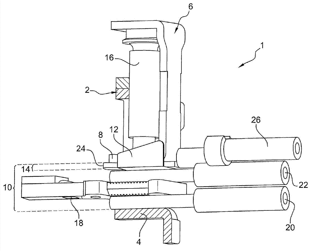
Technical field [0001] The invention relates to an electrical connection terminal and an assembly including the terminal. [0002] The connection terminal according to the present invention may find applications for assembling electric appliances such as electric contactors, for example. Background technique [0003] The electrical contactor is conventionally equipped with a fixed contact support projecting outward from its housing. The fixed contact support is connected on the one hand to the circuit surrounded by the housing, and on the other hand to one or more cables via connecting terminals. [0004] From document FR2766297, it is known that the electrical connection terminal 1 with screws (partly in figure 1 Shown in). Terminal 1 includes: [0005] -Cage (cage) 2, including counter-support wall (counter-support wall) 4; [0006] -The yoke 6, including the supporting wall 8 which defines the first clamping position 10 together with the counter supporting wall 4; [0007] -An addi...

Claims


Application Information

Patent Timeline
IPC IPC(8): H01R11/11H01R4/36
CPCH01R4/38H01R4/363H01R4/36H01R11/01
Inventor 弗兰克·达·西尔瓦
Owner ABB FRANS
Learn More