An output stage circuit of a power amplifier

An output stage circuit, power amplifier technology, applied in the direction of improving amplifiers to reduce temperature/power supply voltage changes, improving amplifiers to reduce nonlinear distortion, etc., can solve problems such as poor stability, unpleasant sound quality, crossover distortion, etc. High performance, reduced circuit cost, effect of solving temperature compensation problem

Active Publication Date: 2016-11-02
广州市迪士普音响科技有限公司
View PDF6 Cites 0 Cited by
  • Summary
  • Abstract
  • Description
  • Claims
  • Application Information

AI Technical Summary

Problems solved by technology

Temperature sampling is only a slowly changing average value, but the temperature of the power tube core changes rapidly, and the ordinary temperature compensation circuit cannot sample and adjust the bias voltage and current in time
This brings about some problems. First, the sound quality is terrible. Many power amplifiers are very good when measuring the rated output distortion, but when listening to music, you can clearly feel "crossover distortion"; second, the stability becomes poor, such as when the power amplifier is turned on in winter. , the bias voltage is high, at this time, if the full power is output, the temperature of the power tube core will rise rapidly, due to the lag of the compensation of the bias circuit, it often leads to failure of the power amplifier due to excessive current

Method used


Image

  • An output stage circuit of a power amplifier
  • An output stage circuit of a power amplifier
  • An output stage circuit of a power amplifier

Examples


no. 1 Embodiment

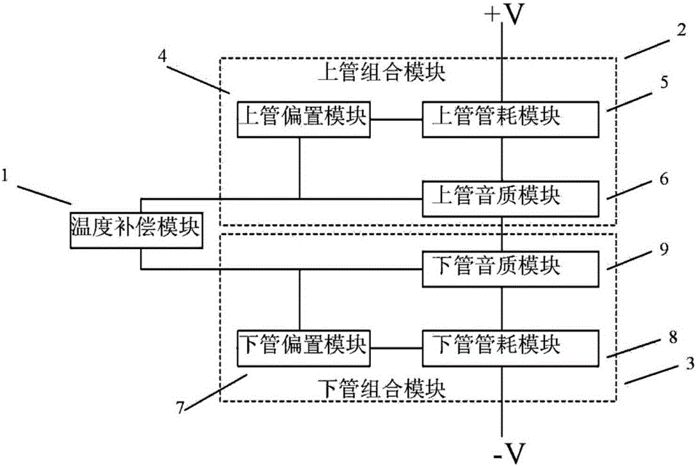
[0033] Relative circuit schematic figure 2 , image 3 In the middle circuit, the transistors in the upper tube consumption module, the upper tube sound quality module, the lower tube tube consumption module and the lower tube sound quality module are all replaced with Darlington tubes, and the corresponding positions in the circuit are increased with resistance.

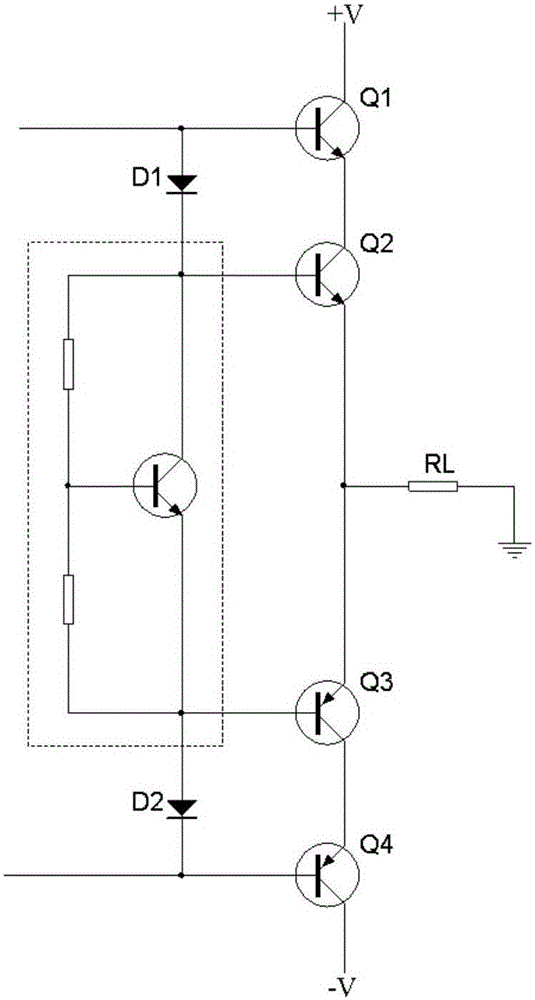
[0034] exist figure 2 In the upper tube tube consumption module circuit, the current magnification factor is: the input current is multiplied by the magnification factor of the first NPN transistor Q1.

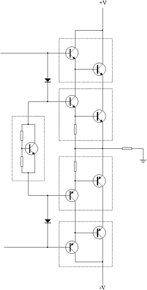
[0035] exist image 3 In the upper tube consumption module circuit, the current magnification factor is: the input current is multiplied by the magnification factor of the first NPN transistor, and then multiplied by the magnification factor of the second NPN transistor.

[0036] It can be seen that the effect of increasing the current of the output stage circuit can be achieved by adding a first-stage current a...

no. 2 Embodiment

[0038] Figure 4 The circuit shown is image 3 The improvement of the circuit shown is also due to the symmetrical structure of the upper and lower modules, and the working principle of the two circuits is similar. Figure 4 The shown circuit adopts the bootstrap circuit to provide the output circuit of the control signal of the upper pipe consumption module and the lower pipe consumption module.

[0039] exist image 3 on the basis of Figure 4 As shown, inductance and capacitance are added in the upper tube combination module. The signal is input from the anode of the first diode. Since the inductance has the inductive reactance characteristic of direct current resistance and alternating current, the dynamic audio signal cannot pass through the inductance, but passes through the first diode and then passes through the Darlington in the sound quality module of the upper tube. The current is amplified by the tube and sent to the load for use. The audio AC signal is fed bac...

no. 3 Embodiment

[0041] Such as Figure 5 , the power supply provides 12V voltage, and supplies power to the pre-transistor of the Darlington tube in the upper tube sound quality module through the pre-transistor of the Darlington tube in the upper tube consumption module. The pre-stage triodes of the above two Darlington tubes are common The collector circuit has only current gain and no voltage gain, and can be powered by a low-voltage power supply; the circuit of the lower tube combination module and the circuit of the upper tube combination module have a symmetrical structure, and can also be powered by a low-voltage power supply.

[0042] The power supply of the power output stage requires a voltage of tens of volts to hundreds of volts, such as Figure 5 , the positive power supply supplies power to the back-stage triode of the Darlington tube in the upper tube sound quality module through the back-stage triode of the Darlington tube in the upper tube consumption module. Since the commo...


PUM


Abstract

The invention discloses an output stage circuit of a power amplifier. The output stage circuit comprises a temperature compensating module, an upper pipe combined module and a lower pipe combined module. Two combined power pipe modules substitute for single output triode in a common circuit, only high voltage and power borne on the triode is taken into consideration of the upper pipe portion, and speed and linear parameters of the triode are paid attention in the lower pipe portion, so that by the low-cost triode, high performance can be achieved, the problem of temperature compensation is effectively solved and circuit cost is reduced. The output stage circuit of the power amplifier can be widely applicable to electronic circuits.

Description

technical field [0001] The invention relates to an electronic circuit, in particular to an output stage circuit of a power amplifier. Background technique [0002] With the development of audio technology, the output power of the power amplifier is getting bigger and bigger, and the output voltage is also rising accordingly. For class AB power amplifiers, power tube components are required to withstand high voltage, fast speed, and good linearity. There are few varieties of power tubes on the market that can meet these requirements at the same time, and even if there are, there are problems of unstable supply and no price advantage. [0003] As we all know, the bias circuit of class AB power amplifier to eliminate "crossover distortion" has temperature compensation characteristics. The temperature sampling is just a slowly changing average value, but the temperature of the power tube core changes rapidly, and the ordinary temperature compensation circuit cannot sample and ...

Claims


Application Information

Patent Timeline
Patent Type & Authority Patents(China)
IPC IPC(8): H03F1/30H03F1/32
Inventor 王齐祥
Owner 广州市迪士普音响科技有限公司
Why Eureka
Try Eureka