Back-to-Back Induction Synchronizers

An inductive synchronizer and a common technology, applied in the field of back-to-back inductive synchronizers, can solve problems such as being difficult to achieve, and achieve the effect of ensuring measurement accuracy and high measurement accuracy

Active Publication Date: 2015-11-18
HARBIN INST OF TECH
View PDF3 Cites 0 Cited by
  • Summary
  • Abstract
  • Description
  • Claims
  • Application Information

AI Technical Summary

Problems solved by technology

However, the accuracy measurement of high-precision induction synchronizers often puts forward higher requirements on the accuracy of measuring equipment, which is often difficult to meet

Method used


Image

  • Back-to-Back Induction Synchronizers
  • Back-to-Back Induction Synchronizers
  • Back-to-Back Induction Synchronizers

Examples


Embodiment Construction

[0014] The present invention will be described in further detail below in conjunction with the accompanying drawings: the present embodiment is implemented on the premise of the technical solution of the present invention, and detailed implementation is provided, but the protection scope of the present invention is not limited to the following embodiments.

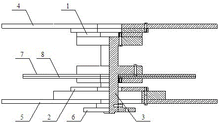
[0015] Such as figure 1 As shown, a back-to-back induction synchronizer involved in this embodiment includes: an upper induction synchronizer 1, a lower induction synchronizer 2, a common rotating shaft system 3, an upper stator tray 4, a lower stator tray 5, and a shaft sleeve 6 , the upper rotor tray 7 and the lower rotor tray 8, the upper end of the upper induction synchronizer 1 is fixedly connected with the common rotating shaft system 3, the upper end of the upper induction synchronizer 1 is fixed with the upper stator tray 4, and the rotating shaft sleeve 6 is fixed on the common The lower part of the rotating shaft...


PUM


Abstract

The invention provides a back-to-back induction synchronizer. An upper induction synchronizer is fixedly connected with the upper end of a common rotating shaft system; an upper stator tray is fixed at the upper end of the upper induction synchronizer; a rotating shaft sleeve is fixed at the lower part of the common rotating shaft system; a lower stator tray is arranged at the upper end of the rotating shaft sleeve; a lower induction synchronizer is arranged at the upper end of the lower stator tray; and an upper rotor tray and a lower rotor tray are fixed at the middle part of the common rotating shaft system, and are parallel to the upper stator tray and the lower stator tray. The back-to-back induction synchronizer adopts an operating principle that after an observation set begins, the upper induction synchronizer and the lower induction synchronizer can rotate together with a shaft, corresponding angular position signals are output in real time by an angle measurement circuit in n measurement positions, and readings of the master induction synchronizer and the slave induction synchronizer are directly read out from an angle display device, and are subtracted for separating error data of the upper induction synchronizer and the lower induction synchronizer by a combination intercomparison method.

Description

technical field [0001] The invention relates to a back-to-back induction synchronizer, belonging to the technical field of induction synchronizers. Background technique [0002] The induction synchronizer is a device that converts linear displacement or angular displacement into electrical signals by using electromagnetic principles. Position measurement using inductosynchronizers is not perfect, such as dimensional deviations caused by insufficient manufacturing accuracy, conditional errors caused by installation and adjustment, and inherent distortion of inductosynchronizer components due to the presence of harmonic magnetic fields and harmonic potentials. Principle errors and so on. As a result of the above phenomena, errors will be introduced into the position measurement of the inductosynchronizer. Inductosynchronizers account for a large proportion of the angular position measurement market, and high precision is a major advantage of them compared to other goniometri...

Claims


Application Information

Patent Timeline
Patent Type & Authority Patents(China)
IPC IPC(8): G01B7/30
Inventor 刘承军邹继斌朱梦龙徐永向胡建辉赵猛江善林赵博王骞
Owner HARBIN INST OF TECH
Why Eureka
Try Eureka