A Correction Method for Angle Tilt of Line Scan Camera

A technology of line array camera and angle tilt, which is applied in the direction of measuring inclination, measuring devices, instruments, etc. It can solve the problems of difficulty in achieving complete consistency and the influence of correction results, and achieve the effect of good stability, high precision and simple operation

Active Publication Date: 2016-01-27
SUZHOU VEGA TECH CO LTD
View PDF5 Cites 1 Cited by
  • Summary
  • Abstract
  • Description
  • Claims
  • Application Information

AI Technical Summary

Problems solved by technology

Then, the resolutions in the X and Y directions of the image are respectively determined by the interval between the image sensor of the line scan camera and the trigger signal, so it is difficult to achieve complete consistency, and correction is required for this
However, in the current existing technology, when the calibration plate is being calibrated, there are requirements for the placement angle of the calibration plate. If there is a deviation, it will have more or less influence on the final calibration result.

Method used


Image

  • A Correction Method for Angle Tilt of Line Scan Camera

Examples


Embodiment 1

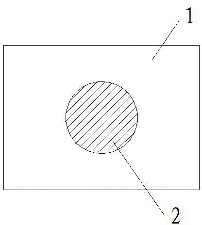
[0021] like figure 1 As shown, for the calibration plate used for calibration in the present invention, the target area of ​​the calibration plate is circular, and there is no requirement for the placement angle of the calibration plate, and it is still circular when rotated at any angle. The diameter of the target area is equal to three-quarters of the scanning width of the line scan camera, and the accuracy of the target area is required to be equal to 1 micron, effectively ensuring the accuracy of the scanning results. The color of the target area is black, and the color of the background area of ​​the calibration plate is white. Since the color of the circular target area of ​​the calibration plate has a high contrast with the background area, it can facilitate fast and convenient scanning.

[0022] The specific steps of the correction method of the present invention are: (1) scan a correction plate with a line array camera to obtain the image of the correction plate; (2) ...

Embodiment 2

[0024] The rest is the same as that of Embodiment 1, except that the diameter of the target area is greater than three quarters of the scan width of the line scan camera, effectively ensuring the accuracy of the scan result.

Embodiment 3

[0026] The rest are the same as in Embodiment 1, except that the color of the target area is white, and the color of the background area is black. The color of the target area and the background area have a high contrast, which can help to scan quickly and conveniently.


PUM


Abstract

The invention discloses a correction method of angle inclination of a linear array camera. The method comprises the following steps: (1) scanning a correction plate by the linear array camera to detect boundary points of object areas on the correction plate; (2) fitting central point linear equations of each boundary point; (3) correcting an inclination angle of the linear array camera along a scanning direction according to an inclination degree of a straight line of the central points; and (4) calculating a length of a longest line of the object areas, and correcting the inclination angle of a scanning surface of the correction camera. The technical scheme is beneficial in that only the correction plate needs to be scanned, correction is carried out through the scanning results, and thus operation is simple, processing algorithm is simple, correction results are good in stability, and precision is high.

Description

technical field [0001] The invention relates to a detection method applied to camera installation angles, in particular to a method for correcting the angle inclination of a line array camera. Background technique [0002] In machine vision systems, image sensors are key components of the entire system. According to the collection method, there are two main categories: area scan camera and line scan camera. Due to its advantages of high scanning frequency and high resolution, line scan cameras are widely used in machine vision systems in the fields of industry, medical treatment, scientific research and security, especially some vision systems that require high-precision measurement. The correct installation angle of the line scan camera should be that the scanning direction is perpendicular to the moving direction of the target to be scanned, and the scanning plane is parallel to the target plane. If there is an angle tilt during the installation of the line scan camera, ...

Claims


Application Information

Patent Timeline
Patent Type & Authority Patents(China)
IPC IPC(8): G01C9/00
Inventor 王彬生杨仁杰
Owner SUZHOU VEGA TECH CO LTD
Why Eureka
Try Eureka