Machining method and special hinged tool post for ultra-long and deep vertical turning

A processing method and vertical lathe technology, which are applied in metal processing equipment and other directions, can solve the problems of inaccurate repeated positioning of processing, cumbersome tool loading process, laborious removal of workpieces, etc., achieving simple structure, convenient picking/putting of workpieces, and quick installation. handy effect

Active Publication Date: 2015-10-28
慈溪汇丽机电股份有限公司
View PDF5 Cites 0 Cited by
  • Summary
  • Abstract
  • Description
  • Claims
  • Application Information

AI Technical Summary

Problems solved by technology

[0003] The present invention aims at the problems of inaccurate processing and repeated positioning in the current processing method, cumbersome tool installation process, low safety factor, and laborious work-piece removal, and proposes a simple structure, high complete coefficient, extremely small repeated positioning error, and quick and convenient installation. Machining method and special hinged tool post for ultra-long and deep vertical turning

Method used


Image

  • Machining method and special hinged tool post for ultra-long and deep vertical turning
  • Machining method and special hinged tool post for ultra-long and deep vertical turning
  • Machining method and special hinged tool post for ultra-long and deep vertical turning

Examples


Embodiment 1

[0033] Embodiment 1 The processing method of the ultra-long depth vertical turning of the present invention comprises the following steps:

[0034] (1) Set the processing program of the workpiece to be processed on the control panel of the lathe;

[0035] (2) Pull the bottom of the cutter bar upwards to the direction where the axis of the cutter bar is perpendicular to the axis of the main shaft, and at the same time make the gear pin socket on the main shaft connector at the position below the tool bar, and then The gear pin is inserted into the gear pin socket to realize the lateral fixation of the knife rod, and install the required tools on the tool mounting frame;

[0036] (3) Move the main shaft, after being adjusted to the processing position of the workpiece to be processed, unplug the gear pin that is positioned at the bottom of the tool bar at this time, so that the tool bar will naturally sag again under the action of gravity;

[0037] (4) Adjust the axis of the cu...

Embodiment 2

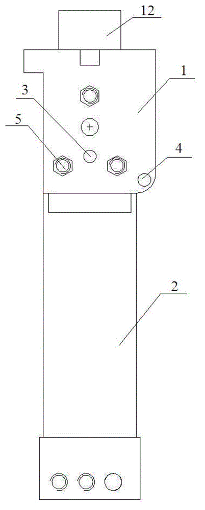
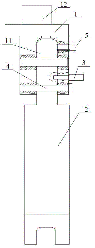
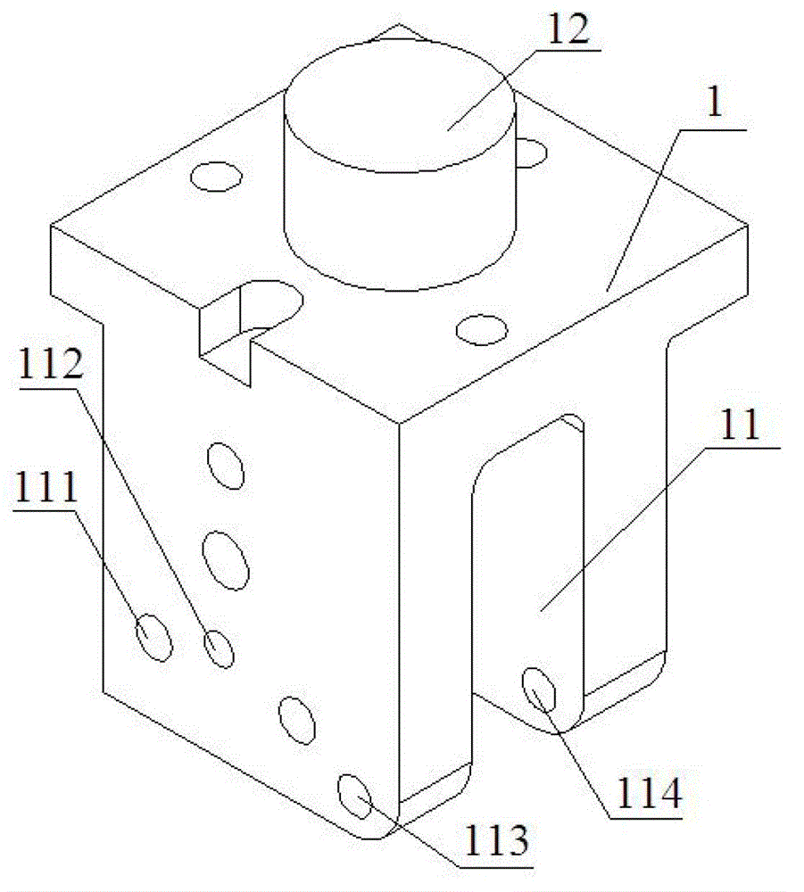
[0040] Embodiment 2 A special hinged tool post constructed according to the processing method described in the present invention, including a main shaft connector 1, a tool bar 2, a positioning plunger 3, a gear pin 4 and a positioning bolt 5, and the upper end of the main shaft connector 1 is Fixed on the main shaft of the lathe, the lower end of the main shaft connector 1 is provided with a strip-shaped tool bar installation groove 11, and a positioning part communicating with the tool bar installation groove 11 is provided on the rib of the tool bar installation groove 11. Bolt holes 111, positioning sockets 112, first gear pin holes 113 and second gear pin holes 114, and the first gear pin holes 113 and the second gear pin holes 114 are respectively located on the cutter bar The same position of the different ribs of the installation groove 11;

[0041] Described cutter bar 2 comprises cutter bar shaft 21 and the tool mounting frame 22 of installing cutter, and described t...


PUM


Abstract

Disclosed are a machining method of ultra-depth vertical turning, and a hinged tool rest special for the same. The method includes: setting a machining program, pulling a tool bar until the axis of the tool bar is perpendicular to the axis of a spindle, moving the spindle, pulling off stop pins after moving the spindle, inserting a positioning insert bar after the axis of the tool bar is superposed with that of the spindle, tightening positioning bolts, and machining a workpiece; after machining, loosening the positioning bolts, pulling off the positioning insert bar to allow the axis of the tool bar to be perpendicular to that of the spindle, re-inserting the stop pins, and taking out the workpiece. The special hinged tool rest comprises a spindle connecting block, a tool bar, a positioning insert bar, stop pins and positioning bolts. The upper end of the spindle connecting block is fixed to a lathe spindle. The lower end of the spindle connecting block is provided with an elongated tool bar mounting groove. The tool bar comprises a tool shank and a tool mounting rack for mounting a tool. The upper end of the tool shank is hinged to a connecting shaft inside the tool bar mounting groove. The machining method and the special hinged tool rest have the advantages that the structure is simple, safety factor is high, repeated positioning has small errors, mounting is quick, and the workpiece is convenient to take and place.

Description

technical field [0001] The invention relates to a processing method for ultra-long and deep vertical turning and a special hinged tool holder, in particular to a method for processing a super-long iron core gear of a large motor base with a C5225 vertical lathe and a special hinged tool holder. Background technique [0002] Use the existing processing method and processing tool to process a large motor frame. The common processing method: 1) Install the knife. This step is quite cumbersome. First, a wooden board should be placed horizontally in the middle of the machine base, and then the knife should be placed on the wooden board. First, adjust the position of the spindle so that the hole of the tool holder is aligned with the axis of the spindle, and then feed the tool axially (this process is more dangerous, if it is not aligned and feed directly), it will cause the board to break and the tool holder to damage the product; 2) Start Processing, each time the spindle is low...

Claims


Application Information

Patent Timeline
Patent Type & Authority Patents(China)
IPC IPC(8): B23B1/00B23B21/00
Inventor 陈洪凯胡光辉
Owner 慈溪汇丽机电股份有限公司
Why Eureka
Try Eureka