
A cable rack

A pay-off frame and cable technology, which is applied in the direction of thin material processing, delivery of filamentous materials, transportation and packaging, etc., can solve the problems of hidden dangers in production safety, high labor intensity of construction personnel, and complicated conditions of electric power construction sites, etc., and achieve reduction The effect of labor intensity, avoiding scattering and intertwining, and occupying a small space

Inactive Publication Date: 2016-08-03
STATE GRID CORP OF CHINA +2
View PDF5 Cites 0 Cited by
  • Summary
  • Abstract
  • Description
  • Claims
  • Application Information

AI Technical Summary

Problems solved by technology

This mode of operation not only requires enough space, but also has a high labor intensity for the construction personnel. At the same time, due to the complicated situation of the electric power construction site, there are also hidden dangers in safety production.

Method used


Image

  • A cable rack
  • A cable rack
  • A cable rack

Examples


Embodiment Construction

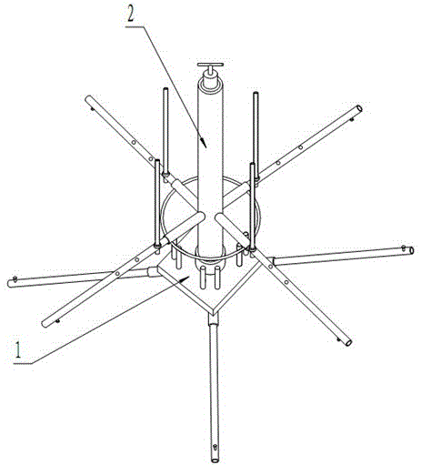
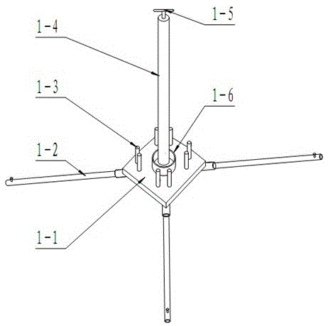
[0022] see figure 1 , the present invention includes a rotating part 2 and a fixed part 1.

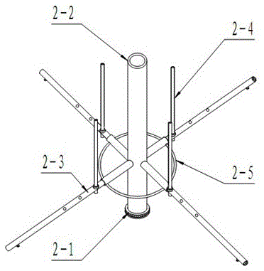
[0023] see image 3 , Figure 4 , Figure 5 , the rotating part 2 of the present invention is composed of a sleeve 2-2, a pressure bearing 2-1, a support seat 2-5, a support arm 2-3 and a limit arm 2-4, and the bottom of the sleeve 2-2 is installed with a pressure Bearing 2-1, the pressure bearing 2-1 is set on the outside of the sleeve 2-2, and it is assembled with the outer wall of the sleeve 2-2 in an interference fit manner, and the support seat 2-5 is fixed on the sleeve 2-2 On the outer wall, a group of support arms 2-3 are evenly distributed along the circumferential direction of the support base 2-5. The support arms 2-3 are detachable structures, and the number thereof is not less than four. Each support arm 2-3 3 are provided with a set of limit arm assembly holes 2-3-1, the number of the limit arm assembly holes 2-3-1 is not less than three, and welding is provided at th...


PUM


Abstract

The invention discloses a cable pay-off stand which is used for solving the problem of laying of cables in bulk. The cable pay-off stand comprises a rotating part and a fixed part, wherein the rotating part is composed of a sleeve, a pressure bearing, a supporting base, supporting arms and limiting arms. The pressure bearing is installed at the bottom of the sleeve, the supporting base is fixed on the outer wall of the sleeve, a group of supporting arms are evenly arranged along the circumference of the supporting base, and the limiting arms are assembled on the supporting arms. The cable pay-off stand has the advantages of being simple in structure, low in cost and convenient to operate, reducing labor intensity of construction staff, occupying small space and reducing safety hazards in using and transportation processes.

Description

technical field [0001] The invention relates to a cable pay-off frame, belonging to the technical field of cable or wire installation. Background technique [0002] During the construction and maintenance of transmission lines, the laying of bulk cables is generally done manually, and the coiled cables are unfolded through a series of actions such as "pulling, throwing, and stretching". This mode of operation not only requires enough space, but also has a high labor intensity for construction personnel. At the same time, due to the complicated situation of the electric power construction site, there are also hidden dangers in safety production. Contents of the invention [0003] The object of the present invention is to aim at the disadvantages of the prior art, and provide a cable pay-off rack with simple structure, easy to carry, and can meet the requirements of laying bulk cables on the construction site. [0004] Problem described in the present invention is realized ...

Claims


Application Information

Patent Timeline
Patent Type & Authority Patents(China)
IPC IPC(8): B65H49/32
Inventor 杨立民姜学军黄波李同盼刘鑫刘仁旺滕向东顾伟胡学文张宏成杨炳维
Owner STATE GRID CORP OF CHINA
Learn More