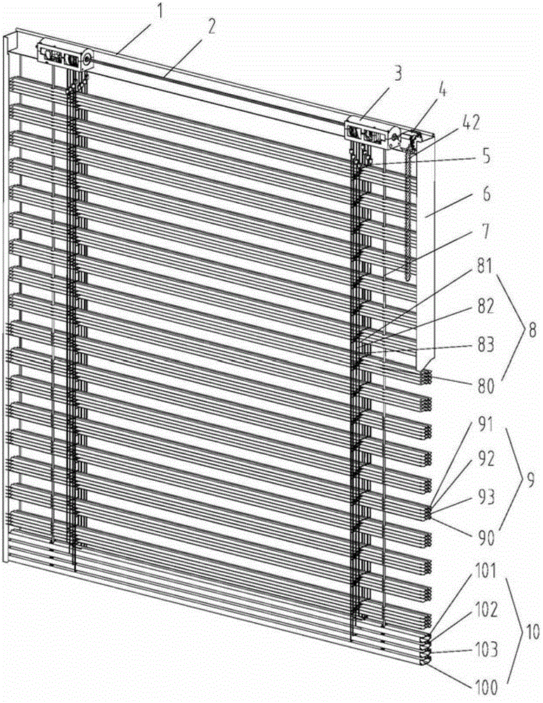
Roller system of louver pin shaft roller mechanism and incomplete gear overturning mechanism
What is AI technical title?
AI technical title is built by Patsnap AI team. It summarizes the technical point description of the patent document.
A technology of rolling wheels and gears, which is applied in the field of variable-pitch combined shutters, and can solve problems such as unpublished transmission mechanisms
Active Publication Date: 2015-03-25
HANGZHOU WOKASOLAR TECH
View PDF8 Cites 3 Cited by
Summary
Abstract
Description
Claims
Application Information
AI Technical Summary
This helps you quickly interpret patents by identifying the three key elements:
Problems solved by technology
Method used
Benefits of technology
Problems solved by technology
However, this invention patent application only discloses the combined structure of the combined louver and the sunshade and light guide effect of the relative lifting and turning of the louver, and does not disclose the transmission mechanism related to the combined louver
Method used
Image
Click on the blue label to locate the original text in one second.
Reading with bidirectional positioning of images and text.
Examples
Embodiment 1
[0109] Embodiment 1: Rotor reel system of variable pitch combined louver with three louver blades
[0110] A movement cycle of the relative lifting and turning of the louvers of the variable-pitch combined louvers with three louvers is: (1) The main louvers 90 are distributed on the window at equal pitches, and the secondary louvers 91, 92 and 93 are stacked on the main On the louvers 90, (corresponding to Figure 75a ), (2) The second hundred blades 91 rise to D relative to the main shutter blades 90 1 -D 2 position, the second two louver blades 92 and the second three louver blades 93 are still superimposed on the main louver blade 90 (corresponding to Figure 75b ), (3) the second hundred blades 91 continue to rise to D relative to the main shutter blades 90 2 position, while the second louver 92 rises to D relative to the main louver 90 2 -D 3 position, the second three louver blades 93 are still superimposed on the main louver blades 90 (corresponding to Figure 75c...
Embodiment 2
[0132] Example 2: Rotor reel system of variable pitch combined louver with three louvers (double half-pitch) Relative lifting and turning of combined louvers for variable pitch combined louver with three times louvers (double half pitch) A cycle of movement is: (1) The main louver blades 90 are distributed on the window at equal pitches, and the secondary louver blades 91, 92 and 93 are stacked on the main louver blade 90 in sequence (corresponding to Figure 76a ). (2) The sub-100 blades 91 and the sub-200 blades 92 are raised to D relative to the main louver blades 90 2 location, (corresponding to Figure 76b ). (3) The sub-two hundred blade 92 and the sub-hundred blade 91 are separated and are in D 2 position, the second one hundred blades 91 and the second three hundred blades 93 rise a distance D relative to the main louver blades 90 3 , at this time the second hundred blades 91 are in D 1 position, the second three hundred blades 93 are in D 3 location, (correspond...
Embodiment 3
[0142] Embodiment 3: Rotor reel system of variable pitch combined louvers with triple louver blades
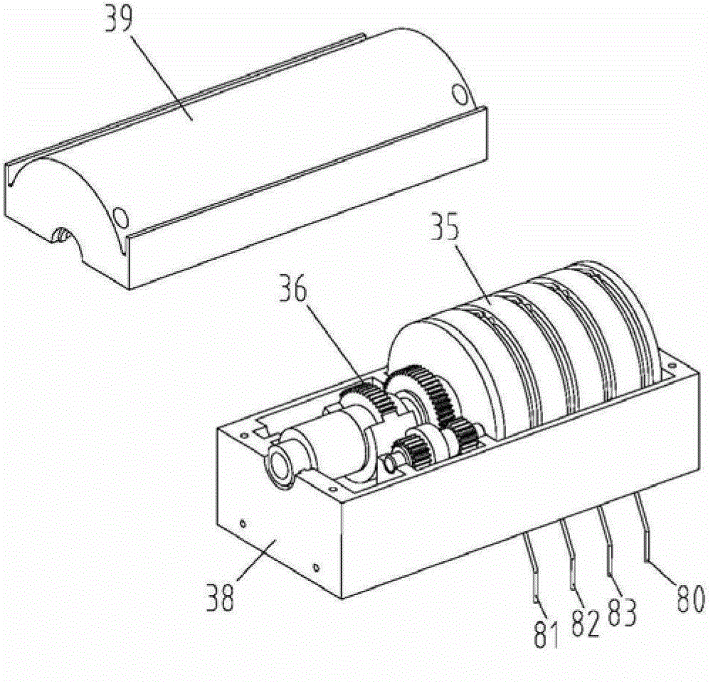
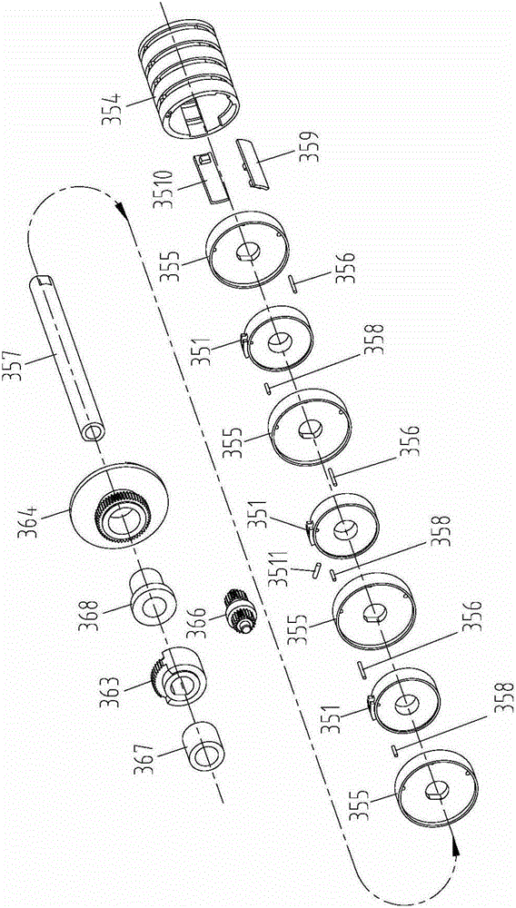
[0143] According to attached Figure 42 , the rotor roller system 3 for variable pitch combined shutters with three louver blades includes a roller mechanism 35 and an incomplete gear turning mechanism 36, and the roller mechanism 35 includes three rotor rollers 351, 352, 353, two Push wheel 355, a rotating shaft 357, a turning cylinder 354, an insert block 359, three short pin shafts 358 and a long pin shaft 356, three rotor scroll wheels 351 and two push wheels 355 are sleeved on the rotating shaft 357 in sequence And installed in the turning cylinder 354, the incomplete gear turning mechanism 36 includes a sleeve 367, a second third gear 363, a second third driven wheel 366, a turning disc sleeve 368 and a turning disc 364, which are axially connected in turn.
[0144] The turning mechanism 36 of the rotor rolling system 3 used for the variable pitch combined shutter with ...
PUM
Abstract
Disclosed is a pin shaft winding wheel mechanism and a winding wheel system having an incomplete gear tilting mechanism for a window blind, wherein a winding wheel mechanism with a shaft pin comprises a base (38) and a top cover (39), a tilting cylinder (354) is provided between the base (38) and the top cover (39), a rotary shaft (357) passes through the tilting cylinder (354) and is mounted on a support seat (384) formed between the base (38) and the top cover (39), at least two push wheels (355) are fixedly connected on the hollow rotary shaft (357) inside the tilting cylinder (354), at least one winding wheel (351) is provided between adjacent push wheels (355), the winding wheel (351) is in a sliding connection with the hollow rotary shaft (357), at least one fan-shaped protrusion (3513) is provided on an outer ring of the winding wheel (351), wherein a hole (3512) is provided radially at one side of one fan-shaped protrusion (3513) and a pin hole (3551) is provided axially on a side edge of the outer winding wheel to make a pin shaft (356) pass through the pin hole (3551) and connect to two upper ends of a secondary ladder cord (8X) wound around the winding wheel outer ring. The secondary ladder cord (8X) is connected to a respective secondary blind slat (9X), an outer ring of the tilting cylinder (354) is provided with at least one annular groove (35X8) and a corresponding groove top part through-hole (3545) so as to enable the two upper ends of a main and the secondary ladder cord (8X) to be wound and nested therein while the secondary ladder cord (8X) enters the tilting cylinder (354) and is connected to the winding wheel (351). The main ladder cord (80) is fixed at the top part of the annular groove (35X8). A side edge of the push wheels (355) is provided with the shaft pin (356). The hollow rotary shaft (357) drives the rotation of the push wheels (355) and via the shaft pin (356) acts on the fan-shaped protrusion (3513) of the winding wheel outer ring to push the winding wheel (351) to rotate. The shaft pins (356) on each push wheel (355) are mutually spaced apart and provided with an angular difference, such that the winding wheels (351) are driven in turn thus raising in succession the respective secondary blind slats (9X) connected to the secondary ladder cord (8X) wound on the winding wheel (351). The winding wheel system having an incomplete gear tilting mechanism comprises the winding wheel mechanism with the shaft pin. The winding wheel system can control the lifting and tilting of the secondary blind slats (9X) and the tilting of main blind slats (90).
Description
technical field [0001] The invention relates to a variable-pitch combined louver, in particular to a reel system for the louver to control the lifting and turning motion of the louver blades. Background technique [0002] The traditional blinds are composed of louver blades with an arc-shaped cross section, lift ropes, ladder belts, top rails and bottom rails. A rotary drive with self-locking function, a rotating shaft, and several winding lifts are installed in the top rail. The rope is used to control the reel of the ladder belt. The rotating shaft passes through the rotary driver and the reel. A ladder belt is provided between the top rail and the bottom rail. The lower end of the ladder belt is fixedly connected with the bottom rail. On the reel, a plurality of louvers arranged in parallel are worn in the horizontal cable of the ladder belt. A perforation is set at the symmetrical center of the cross section of the louver to allow the lifting rope to pass through. The lo...
Claims
Application Information
Patent Timeline
Application Date:The date an application was filed.
Publication Date:The date a patent or application was officially published.
First Publication Date:The earliest publication date of a patent with the same application number.
Issue Date:Publication date of the patent grant document.
PCT Entry Date:The Entry date of PCT National Phase.
Estimated Expiry Date:The statutory expiry date of a patent right according to the Patent Law, and it is the longest term of protection that the patent right can achieve without the termination of the patent right due to other reasons(Term extension factor has been taken into account ).
Invalid Date:Actual expiry date is based on effective date or publication date of legal transaction data of invalid patent.

