Conductive wire batch grabbing device

A technology for grabbing devices and conductive wires, which is applied in the field of batch grabbing devices for conductive wires, and can solve problems such as simple and convenient grabbing devices that do not exist in loop-forming card-issuing lines

Pending Publication Date: 2022-07-29
CHANGZHOU JINKANG PRECISION MECHANISM
View PDF0 Cites 0 Cited by
  • Summary
  • Abstract
  • Description
  • Claims
  • Application Information

AI Technical Summary

Problems solved by technology

[0005] The purpose of the present invention is to solve the shortcomings in the prior art that there is no device for simple and convenient grasping of the looped hairpins when the four-layer cable of the motor stator is arranged in the application, and proposes a conductive Line batch grabbing device

Method used


Image

  • Conductive wire batch grabbing device
  • Conductive wire batch grabbing device
  • Conductive wire batch grabbing device

Examples


Embodiment

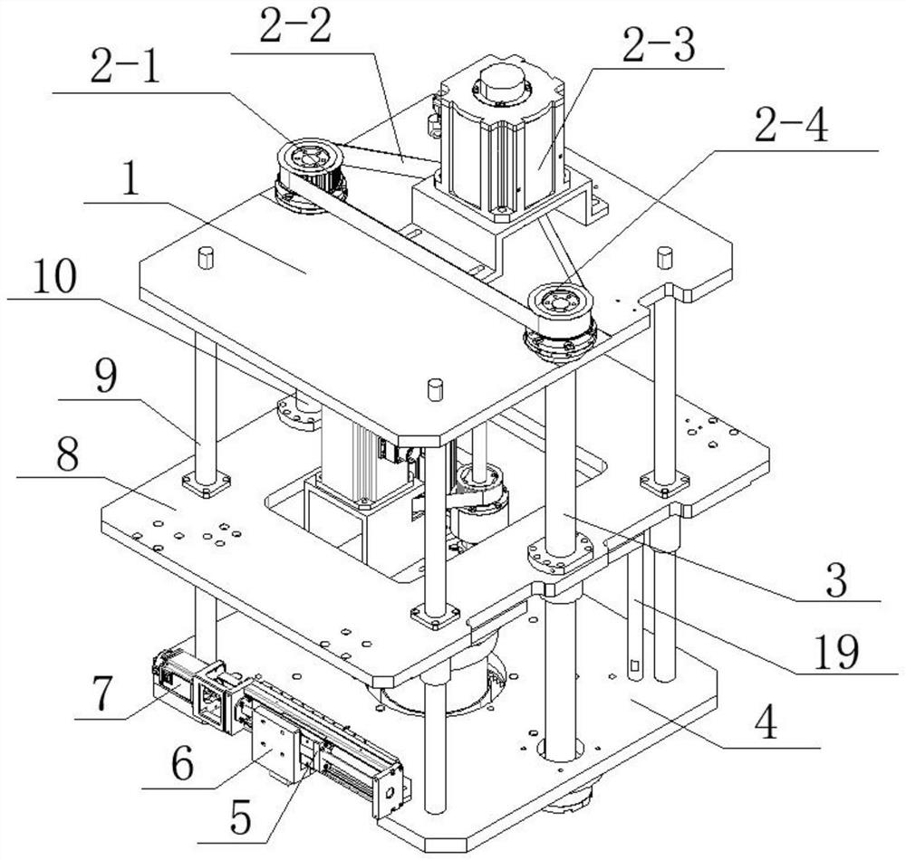
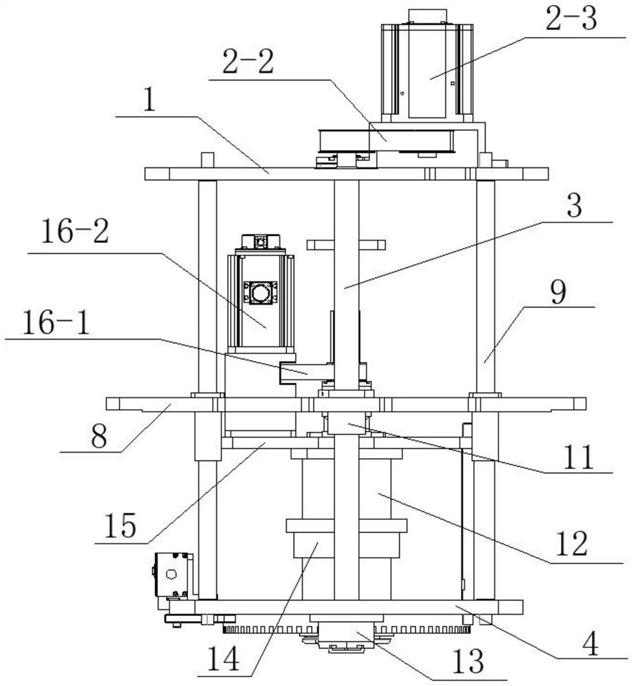
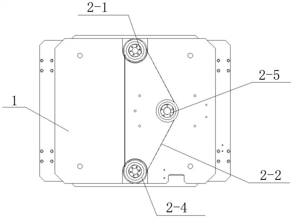
[0042] Example: refer to Figure 1-15 , a batch grabbing device for conductive wires, comprising a lifting mechanism 1 2 installed above the top plate 1, the lifting mechanism 1 2 includes a lifting motor 1 2-3 that controls the rotation of the driving wheel 1 2-5, and is driven by a synchronous belt 1-2- 2 Connect the synchronous wheel 1 2-4 and the synchronous wheel 2 2-1 which rotate with the driving wheel 1 2-5, the synchronous wheel 1 2-4 is fixedly connected with the lead screw 1 3, and the synchronous wheel 2-1 is connected with the lead screw 2 10 Fixed connection. Bearings are fitted inside the synchronizing wheel 1 2-4 and the synchronizing wheel 2 2-1, and the bearings are matched with the outer rings of the lead screw one 3 and the lead screw two 10;

[0043] The moving assembly is controlled by the lifting mechanism one 2 and connects the top plate 1 and the bottom plate 4. The moving assembly includes a nut one 11 connected with the outer ring of the lead screw o...


PUM


Abstract

The invention relates to the technical field of motor accessory production equipment, in particular to an electric lead batch grabbing device. Comprising a first lifting mechanism installed above a top plate, a moving assembly which is controlled by the first lifting mechanism to move and is connected with the top plate and a bottom plate, second lifting mechanisms arranged on a mounting plate, a tensioning mechanism arranged between the second lifting mechanisms, and a clamping assembly which is arranged below the bottom plate in cooperation with the tensioning mechanism and is controlled by a power assembly to move to clamp a hairpin line. According to the invention, the power assembly controls the movement of the tooth protection movable disc and drives the pin rod to slide in the arc-shaped hole, and the pin rod drives the wire clamping tooth block to move in the clamping groove, so that one end of the wire clamping tooth block is controlled to abut against the outer surface of the looped hairpin wire, and the looped hairpin wire is fixedly clamped by the internal and external cooperation of the tensioning mechanism contacted with the looped hairpin wire.

Description

technical field [0001] The invention relates to the technical field of production equipment for motor parts, in particular to a batch grabbing device for conductive wires. Background technique [0002] The stator is the fixed part of the machine. The stator consists of three parts: the stator core, the stator winding and the frame. The main function of the stator is to generate a rotating magnetic field, while the main function of the rotor is to be cut by magnetic lines of force in the rotating magnetic field to generate current. [0003] There are wires arranged on the stator of the motor. A motor with four layers of cables needs to be arranged with four layers of cables on its stator. Currently, for the hairpin coils that have been arranged in a circle, it is necessary to pass the grasping device. The coiled hairpin line is grabbed and moved to the next transfer equipment, which is convenient for the subsequent processing of the hairpin line. However, there is no related...

Claims


Application Information

Patent Timeline
Patent Type & Authority Applications(China)
IPC IPC(8): H02K15/06
CPCH02K15/064
Inventor 钟仁康杨烨胡浪
Owner CHANGZHOU JINKANG PRECISION MECHANISM
Why Eureka
Try Eureka