
Portable direct current test discharging rod

A DC test, discharge rod technology, applied in the direction of testing dielectric strength, circuits, resistors, etc., can solve the problems of small distance, unsafe, easy to damage, etc., to achieve the effect of good use effect and improved service life

Active Publication Date: 2013-08-28
STATE GRID CORP OF CHINA +1
View PDF6 Cites 8 Cited by
  • Summary
  • Abstract
  • Description
  • Claims
  • Application Information

AI Technical Summary

Problems solved by technology

[0003] In the cable DC withstand voltage test, the discharge rods provided by various manufacturers are unsafe and easy to damage due to their small capacity and small distance (especially during the 35KV cable test), which affects the safety of personnel and equipment.

Method used


Image

  • Portable direct current test discharging rod

Examples


Embodiment Construction

[0019] The technical solution of the present invention will be described in detail below in conjunction with the accompanying drawings.

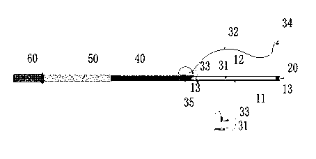
[0020] Such as figure 1 As shown, a portable DC test discharge rod provided by the present invention, the discharge rod includes:

[0021] A resistance element, the resistance element comprising: a resistance housing 11, a water resistance 12 located in the resistance housing and pipe plugs 13 respectively arranged at both ends of the resistance housing; preferably, the water resistance 12 is distilled water;

[0022] a conductive pin 20 fixedly connected to the first end of the resistance element;

[0023] a discharge grounding device fixedly connected to the second end of the resistance element;

[0024] An insulating telescopic tube 40 fixedly connected to the resistance element;

[0025] an insulating tube 50 fixedly connected to the insulating telescopic tube; and

[0026] An insulating handle 60 fixedly connected to the insulating ...


PUM


Abstract

The invention discloses a portable direct current test discharging rod which comprises a resistive element, an electric-conduction needle, a discharging grounding device, an insulating extension tube, an insulating tube and an insulating handle, wherein the resistive element comprises a resistive shell, a water resistor and casing caps. The water resistor is located in the resistive shell. The casing caps are arranged at the two ends of the resistive shell respectively. The electric-conduction needle is fixedly connected at a first end of the resistive element. The discharging grounding device is fixedly connected at a second end of the resistive element. The insulating extension tube is fixedly connected with the resistive element. The insulating tube is fixedly connected with the insulating extension tube. The insulating handle is fixedly connected with the insulating tube. The discharging grounding device comprises a discharging insulated wire socket and a discharging insulated wire. The discharging insulated wire socket is arranged on the resistive shell in an embedded mode. The discharging insulated wire is fixedly arranged on the insulating extension tube. A discharging insulated wire plug is arranged at a first end of the discharging insulated wire. A discharging grounding clamp is arranged at a second end of the discharging insulated wire. The discharging rod is large in capacity, long in measurable distance, safe, long in service life, low in cost and convenient to carry and has very good application prospects.

Description

technical field [0001] The invention relates to a discharge device, in particular, the invention relates to a portable DC test discharge rod. Background technique [0002] With the rapid development of China's economy and the continuous advancement of urbanization, various types of electrical equipment have increased significantly, especially the application of cables and their electrical equipment is more common. In order to ensure the safe operation of electrical equipment, it is necessary to carry out the DC voltage withstand test of cables. The power cable DC voltage withstand test is the most important item in the power cable electrical test project. After the cable withstand voltage test is completed, the residual charge in the cable core must be discharged through a nominal 0.1-0.2 megohm resistance. If the discharge is not carried out or the discharge is not complete, the safety of personnel and equipment will be endangered. It can be seen that the cable test di...

Claims


Application Information

Patent Timeline
Patent Type & Authority Applications(China)
IPC IPC(8): G01R31/12H01R31/06H01C11/00
Inventor 陈惠民
Owner STATE GRID CORP OF CHINA
Learn More