Automatic demand response system and automatic demand response method

A demand-response, automatic technology, applied in the direction of AC network circuits, electrical components, circuit devices, etc., can solve the problems of high peak load, waste of electric energy and cost, and large power grid impact, achieve real-time accurate power grid load, and optimize resources. The effect of combining and balancing grid load

Active Publication Date: 2013-08-28
SHENYANG INST OF AUTOMATION GUANGZHOU CHINESE ACAD OF SCI
View PDF4 Cites 43 Cited by
  • Summary
  • Abstract
  • Description
  • Claims
  • Application Information

AI Technical Summary

Problems solved by technology

The main problems facing my country's electricity demand are as follows: (1) Distributed new energy grid connection: It is estimated that by 2020, the power generation capacity of new energy will reach 150 million kW. Due to the volatility and intermittent nature of new energy power generation, after grid connection The impact on the power grid is very large, and the power grid side is required to increase the system backup to maintain the normal supply of electric energy; (2) The peak load is large, but the problem of short running time: the peak load characteristics of my country are as follows: more than 95% of the peak load for one year The operating time is less than 100 hours, which leads to the low operating efficiency of the generator set added to cope with the peak load, resulting in serious waste of electric energy and cost
However, the application demand response system is only for key users and key load types of power load equipment data collection information and detailed analysis of load characteristics, and cannot analyze the power consumption of each power load equipment, distributed energy generation and energy storage equipment. energy storage, etc.
Therefore, the power supply system cannot accurately grasp the power consumption, power generation and energy storage of power users in real time, and cannot balance the grid load accurately in real time.

Method used


Image

  • Automatic demand response system and automatic demand response method
  • Automatic demand response system and automatic demand response method
  • Automatic demand response system and automatic demand response method

Examples


Embodiment

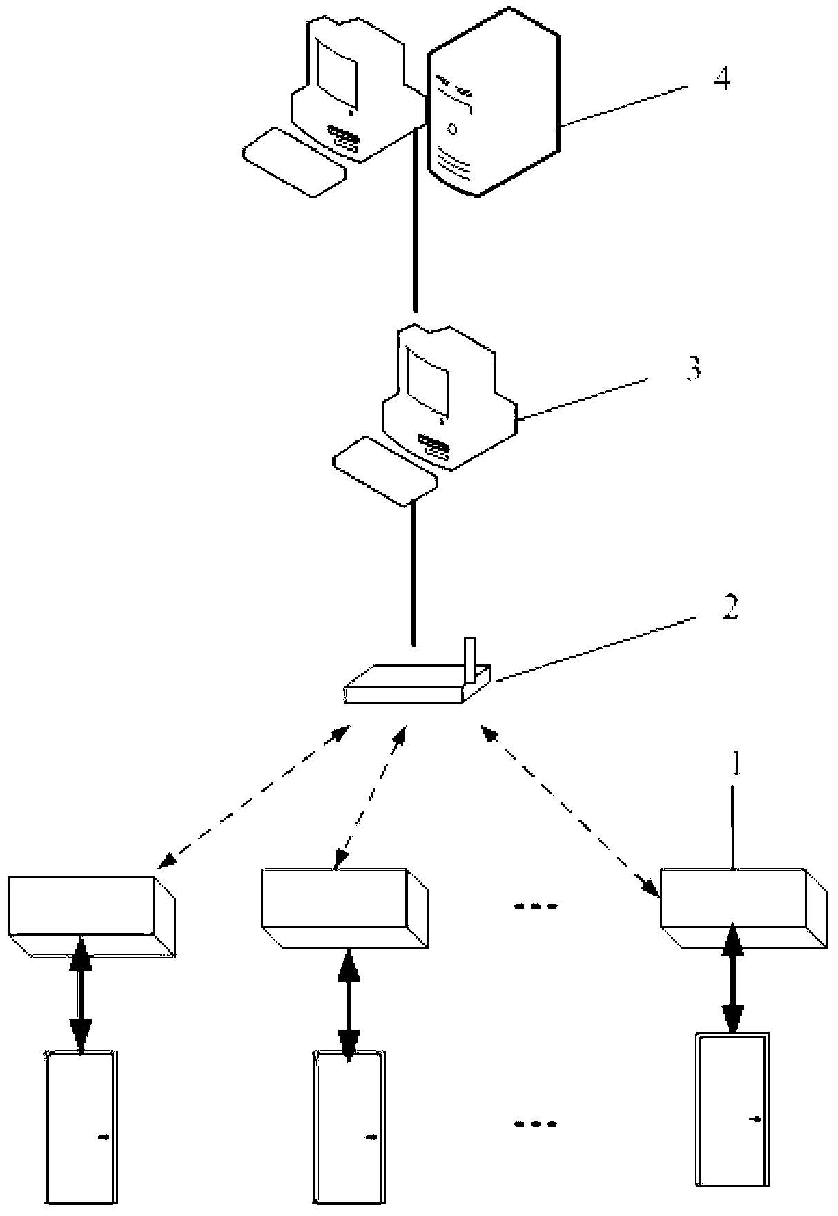
[0044] Such as figure 1 As shown, this embodiment discloses an automatic demand response system, including an EDR controller 1, a multi-protocol communication gateway 2, a DR client 3 and a DRAS4; the EDR controller 1 is connected to the DR client 3 through a multi-protocol communication gateway 2 , the DR client 3 is connected to the DRAS4. Each electric load device, distributed energy source and energy storage device is connected with an EDR controller 1 .

[0045] The EDR controller 1 is wirelessly connected to the multi-protocol communication gateway 2, and the DR client 3 is respectively connected to the multi-protocol gateway 2 and the DRAS4 through Ethernet. Among them, the multi-protocol communication gateway supports Modbus, BACnet, M-Bus, LonWorks and other bus protocols, supports Ethernet, RS232, RS485, USB and other interfaces, and can be easily connected to the local control network or directly connected to the local computer.

[0046] EDR controllers include HA...


PUM


Abstract

The invention discloses an automatic demand response system and an automatic demand response method. The system comprises an EDR (Equipment Demand Response) controller, a multi-protocol communication gateway, a DR (Demand Response) client and a DRAS (Demand Response Automation Server), wherein the EDR controller is connected with the DR client through the multi-protocol communication gateway, and the DR client is connected with the DRAS. The EDR controller collects electric power data of each electric load device, distributed energy source and an energy storage device, and transfers the electric power data to the DRAS through the DR client. The DRAS sends the electricity price information set by a DR center and demand response events to the DR client. The control measure is made by the DR client, and the EDR controller controls the running states and the running modes of each electric load device, the distributed energy source and the energy storage device according to the control measure. The automatic demand response system and the automatic demand response method provided by the invention have the advantages of accurately balancing the power grid load in real time, reducing the impact of new energy on-grid on a power grid, and improving the stability of the power grid.

Description

technical field [0001] The invention belongs to the technical field of smart grids, and in particular relates to an automatic demand response system and an automatic demand response method. Background technique [0002] Electricity is the main form of energy in countries around the world today. In recent years, with the rapid economic development and the increasingly severe energy crisis, energy saving and consumption reduction has become a worldwide theme. The main problems facing my country's electricity demand are as follows: (1) Distributed new energy grid connection: It is estimated that by 2020, the power generation capacity of new energy will reach 150 million kW. Due to the volatility and intermittent nature of new energy power generation, after grid connection The impact on the power grid is very large, and the power grid side is required to increase the system backup to maintain the normal supply of electric energy; (2) The peak load is large, but the problem of sh...

Claims


Application Information

Patent Timeline
Patent Type & Authority Applications(China)
IPC IPC(8): H02J3/00
Inventor 肖金超程海梅何杰刘继海邓龙辉
Owner SHENYANG INST OF AUTOMATION GUANGZHOU CHINESE ACAD OF SCI
Why Eureka
Try Eureka