Light reflector and surface light source device using same
A light reflector and reflectivity technology, applied in the direction of electric light sources, reflectors, lighting devices, etc., can solve the problems of low rigidity, achieve high brightness, improve brightness unevenness, and excellent dimensional stability
- Summary
- Abstract
- Description
- Claims
- Application Information
AI Technical Summary
Problems solved by technology
Method used
Image
Examples
Embodiment
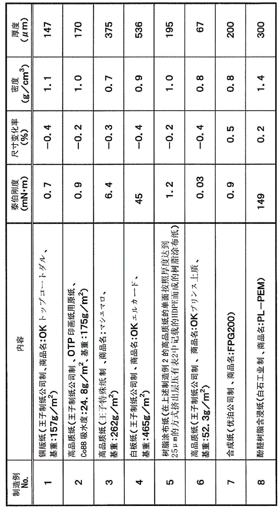
[0111] Hereinafter, the present invention will be described more concretely using production examples, examples, comparative examples, and test examples. The materials, usage amounts, ratios, operations and the like shown below can be appropriately changed without departing from the gist of the present invention. Therefore, the scope of the present invention is not limited to the specific examples shown below. In addition, the summary of the paper material used in the Example of this invention and a comparative example is shown in Table 1.
[0112] [Table 1]
[0113]
manufacture example 1~4
[0116] Using an extruder set at 250° C., a composition for a support layer (a) in which materials described in Table 2 were mixed at a compounding ratio described in Table 3 was melt-kneaded. Thereafter, this was extruded into a sheet and cooled to about 60° C. with a cooling roll to obtain a support layer (a). This support layer (a) was reheated to 145 degreeC, and it stretched in the longitudinal direction at the magnification shown in Table 3 using the peripheral speed difference of several roll groups. Next, using an extruder set at 250°C, the composition for the surface layer (b) in which the materials described in Table 2 were mixed at the compounding ratio described in Table 3 was melt-kneaded, and the composition obtained above was melt-extruded. Both surfaces of the support layer (a) are laminated so as to form a surface layer (b) / support layer (a) / surface layer (b) to obtain a laminate. Next, this laminate was reheated to 160° C., and stretched in the transverse dir...
manufacture example 5
[0118] The composition for the support layer (a) in which the materials described in Table 2 were mixed at the compounding ratio described in Table 3 and the compounding ratio described in Table 3 were mixed using three extruders set at 250° C. The composition for the surface layer (b) of the material described in Table 2 was melt-kneaded. Next, these compositions are laminated in the form of surface layer (b) / support layer (a) / surface layer (b) in a multi-layer mold, extruded into a sheet, and cooled to about 60°C with a cooling roll. °C to obtain laminates. This laminate was reheated to 145° C., and stretched in the longitudinal direction at the magnification described in Table 3 by utilizing the peripheral speed difference of a plurality of roll groups. Next, this laminate was reheated to 160° C., and stretched in the transverse direction at the ratios described in Table 3 by a tenter. Thereafter, after annealing at 160° C., it was cooled to 60° C., and the edges were cut...
PUM
| Property | Measurement | Unit |
|---|---|---|
| density | aaaaa | aaaaa |
| thickness | aaaaa | aaaaa |
| particle size | aaaaa | aaaaa |
Abstract
Description
Claims
Application Information
 - R&D
- Intellectual Property
- Life Sciences
- Materials
- Tech Scout
- Unparalleled Data Quality
- Higher Quality Content
- 60% Fewer Hallucinations
Browse by: Latest US Patents, China's latest patents, Technical Efficacy Thesaurus, Application Domain, Technology Topic, Popular Technical Reports.
© 2025 PatSnap. All rights reserved.Legal|Privacy policy|Modern Slavery Act Transparency Statement|Sitemap|About US| Contact US: help@patsnap.com


