Driving method

a liquid crystal display and driving method technology, applied in the direction of instruments, static indicating devices, etc., can solve the problems of affecting the normal brightness of the display, the risk of hurting the eyes of viewers, and the heavy weight of the electric gun, so as to reduce the mura caused by the line, and improve the non-uniform brightness

Active Publication Date: 2012-04-24
AU OPTRONICS CORP
View PDF23 Cites 7 Cited by
  • Summary
  • Abstract
  • Description
  • Claims
  • Application Information

AI Technical Summary

Benefits of technology

[0010]In the present invention, the pixel units are enabled through different sequences in several consecutive frame times, so as to improve the non-uniform brightness due to capacitance coupling effects between the pixel units, thereby restraining the line mura caused by the non-uniform brightness.

Problems solved by technology

Although the conventional CRT has many advantages, the design of the electron gun renders it heavy, bulky and energy wasting.
Moreover, there is always some potential risk of hurting viewer's eyes due to its emission of some radiation.

Method used


Image

  • Driving method
  • Driving method
  • Driving method

Examples


first embodiment

The First Embodiment

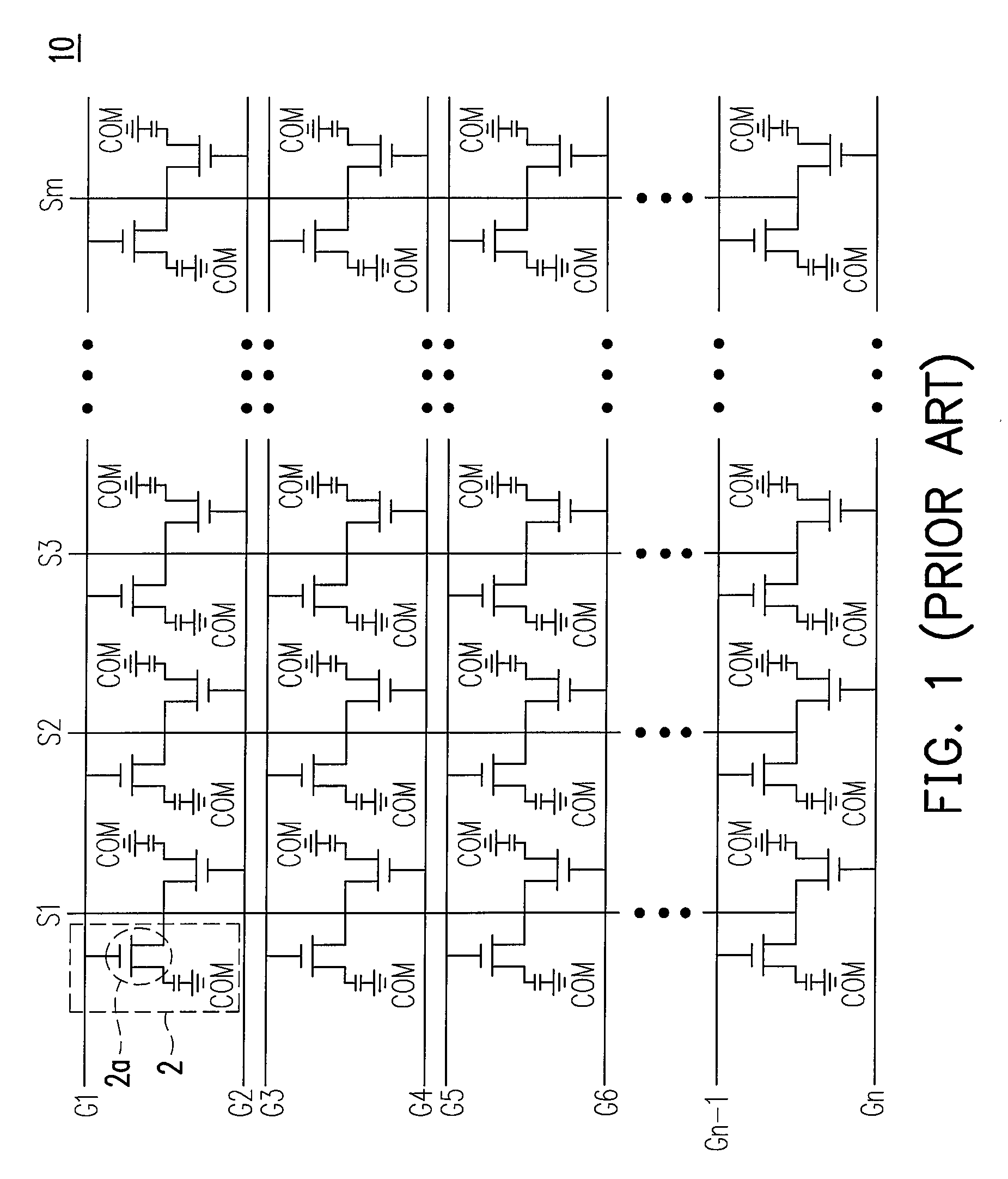
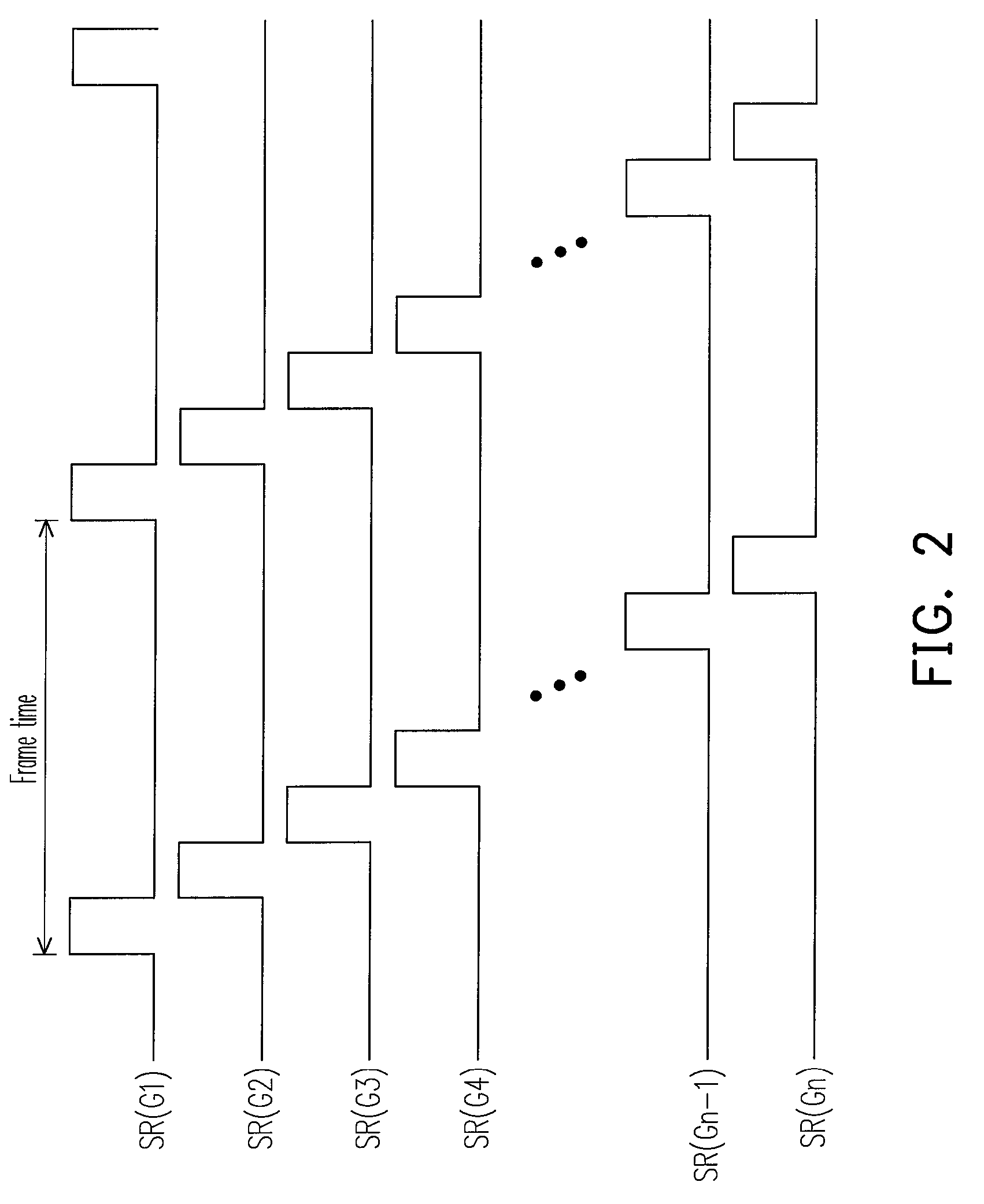
[0022]FIG. 3A is a display panel according to a first embodiment of the present invention, and FIG. 3B is a timing diagram of scanning control signals SR1(G1)-SR1(G2n) according to the first embodiment of the present invention. Referring to FIGS. 3A and 3B, a display panel 10′ includes a plurality of scan lines G1-G2n, a plurality of data lines S1-Sm, and a plurality of pixel units 2 having active devices 2a, wherein n, m are positive integers. The scan lines G1-G2n and the data lines S1-Sm are electrically connected to the active devices 2a of the pixel units 2 correspondingly. In this embodiment, all the pixel units 2 are divided into a plurality of display bands 4, and each of the display bands 4 is constituted by pixel units 2 controlled by two adjacent scan lines. The pixel units 2 in each of the display bands 4 are driven by the corresponding scan lines G1-G2n and corresponding data lines S1-Sm. The scanning control signals SR1(G1)-SR1(G2n) are respectively...

second embodiment

The Second Embodiment

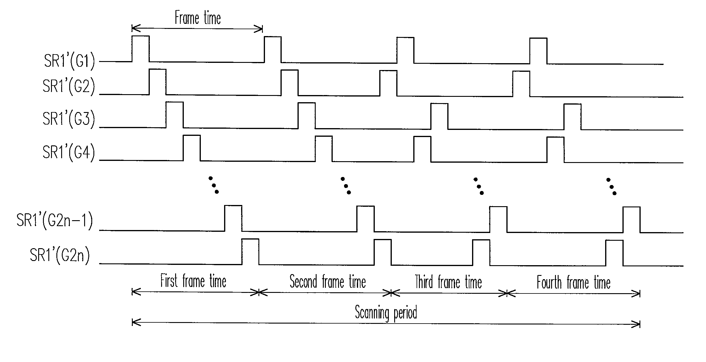
[0028]FIG. 4 is a timing diagram of a driving method according to a second embodiment of the present invention. Referring to FIG. 4, in this embodiment, the scanning period is set to be four frame times. In the first and second frame times, the enable signal of the scanning control signals SR1′(G1)-SR1′(G2n) sequentially enables the pixel units 2 controlled by the scan lines G1, G2, G3, G4, . . . , G2n−1, G2n in each row. In the third and fourth frame times, the enable signal of the scanning control signals SR1′(G1)-SR1′(G2n) sequentially enables the pixel units 2 controlled by the scan lines G2, G1, G4, G3, . . . G2n, G2n−1 in each row.

[0029]In this embodiment, each of the display bands 4 is also constituted by pixel units 2 controlled by two adjacent scan lines. In the first and second frame times, the pixel units 2 controlled by the odd scan lines in the same display band 4 are enabled first, and then the pixel units 2 controlled by the even scan lines are en...

third embodiment

The Third Embodiment

[0031]FIG. 5A is a display panel according to a third embodiment of the present invention, and FIG. 5B is a timing diagram of a driving method of the display panel in FIG. 5A. In the first and second embodiments, each of the display bands 4 is constituted by pixel units 2 controlled by two adjacent scan lines. However, in the present embodiment, each of the display bands 4 is constituted by pixel units 2 controlled by three adjacent scan lines, as shown in FIG. 5A. A detailed description is illustrated below with reference to FIGS. 5A and 5B.

[0032]Referring to FIG. 5B, in the first frame time, the enable signal of the scanning control signals SR2(G1)-SR2(G3n) sequentially enables the pixel units 2 controlled by the scan lines G1, G2, G3, G4, G5, G6, . . . , G3n−2, G3n−1, G3n in each row. In the second frame time, the enable signal of the scanning control signals SR2(G1)-SR2(G3n) sequentially enables the pixel units 2 controlled by the scan lines G3, G1, G2, G6, G...


PUM


Abstract

A driving method for driving a display panel is provided. The display panel includes a plurality of scan lines, a plurality of data lines, and a plurality of pixel units electrically connected to the scan lines and the data lines. The driving method comprises enabling the pixel units controlled by the scan lines through different scanning sequences and inputs image data to the pixel units via the data lines in several consecutive frame times, wherein capacitance coupling effects between the pixel units are varied depending on the scanning sequences. Accordingly, the line mura caused by the capacitance coupling effect is restrained.

Description

CROSS-REFERENCE TO RELATED APPLICATION[0001]This application claims the priority benefit of Taiwan application serial no. 96112825, filed Apr. 12, 2007. All disclosure of the Taiwan application is incorporated herein by reference.BACKGROUND OF THE INVENTION[0002]1. Field of the Invention[0003]The present invention relates to a driving method. More particularly, the present invention relates to a driving method for a liquid crystal display (LCD).[0004]2. Description of Related Art[0005]The proliferation of multi-media systems in our society depends to a large extent on the progressive development of semiconductor devices and display devices. Display devices such as the cathode ray tube (CRT) have been used for quite some time due to its remarkable display quality, reliability and low cost. Although the conventional CRT has many advantages, the design of the electron gun renders it heavy, bulky and energy wasting. Moreover, there is always some potential risk of hurting viewer's eyes ...

Claims


Application Information

Patent Timeline
Patent Type & Authority Patents(United States)
IPC IPC(8): G09G3/34
CPCG09G3/20G09G2300/08G09G2310/02G09G2320/0209
Inventor WANG, TSANG-HONGCHANG, FANG-LINLIN, YUN-CHUNG
Owner AU OPTRONICS CORP
Why Eureka
Try Eureka