Automotive headlamp cleaner nozzle

A technology for cleaners and automobiles, applied in the direction of vehicle cleaning, vehicle maintenance, transportation and packaging, etc., can solve the problem of different fixing devices, and achieve the effect of preventing splashing everywhere.

Inactive Publication Date: 2013-09-04
SUZHOU BODENA TECH
View PDF7 Cites 0 Cited by
  • Summary
  • Abstract
  • Description
  • Claims
  • Application Information

AI Technical Summary

Problems solved by technology

However, the existing automobile headlight nozzles are directly arranged around the automobile hea

Method used


Image

  • Automotive headlamp cleaner nozzle
  • Automotive headlamp cleaner nozzle

Examples


Example Embodiment

[0013] In order to make the object, technical solution and advantages of the present invention clearer, the present invention will be further described in detail below in conjunction with the accompanying drawings and embodiments. It should be understood that the specific embodiments described here are only used to explain the present invention, not to limit the present invention.

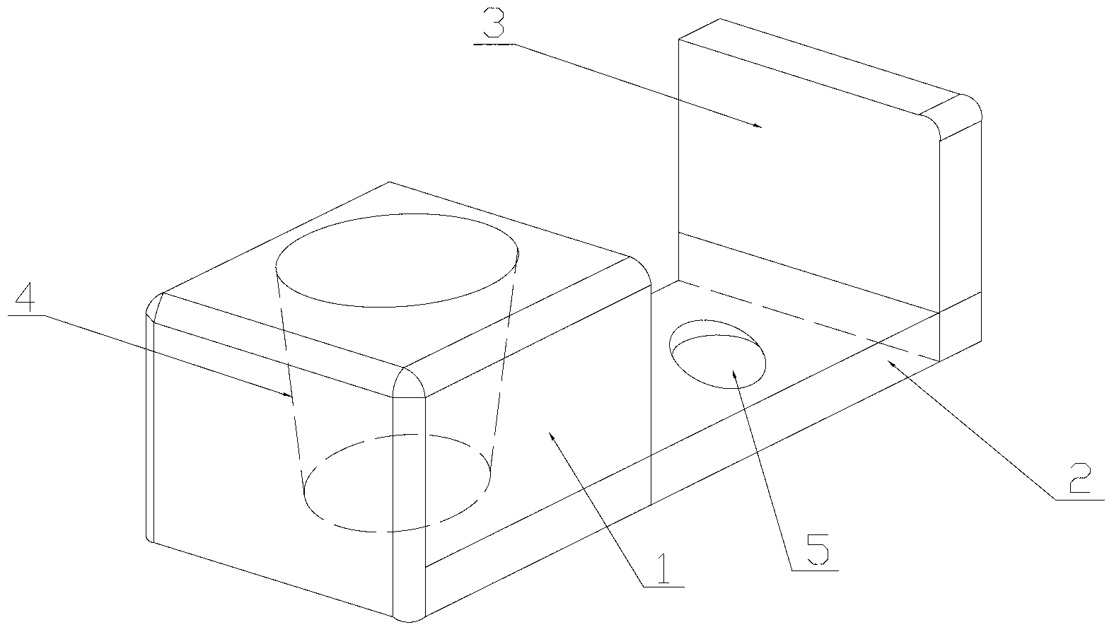
[0014] The first embodiment of the nozzle of the automobile headlight washer of the present invention is as follows: figure 1 As shown, it includes a mounting base 1 and a clamping plate 2 connected to the mounting base 1. A one-way pipe 4 is inserted into the mounting base 1, a through hole 5 is provided on the clamping plate 2, and the clamping plate 2 is also provided with a A baffle 3 is provided, and the baffle 3 is located outside the through hole 5 .

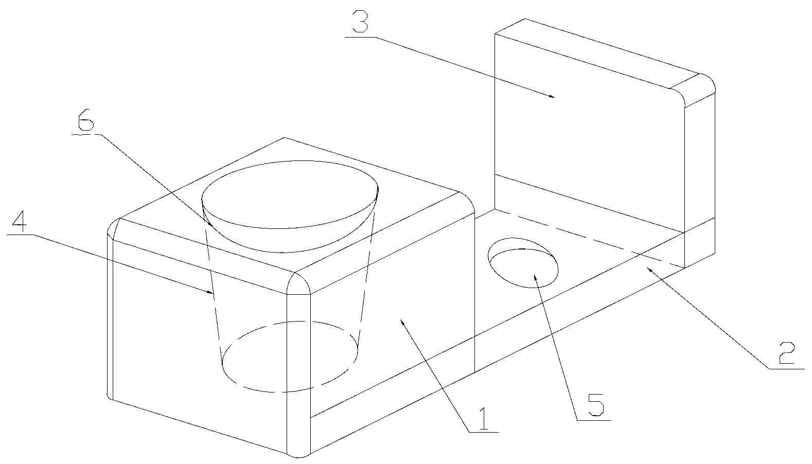
[0015] figure 2 It is the schematic diagram of the three-dimensional structure of the second embodiment of the nozzle of the automobile he...


PUM


Abstract

The invention relates to an automotive headlamp cleaner nozzle comprising a mounting seat and a clamping plate connected to the mounting seat. A one-way tube is inserted in the mounting seat. The clamping plate is provided with a through hole. The clamping plate is further provided with a retainer plate outside the through hole. Preferably, the mounting seat is provided with a positioning post projecting from the surface of the mounting seat. The tail end of the one-way tube is fixed on the positioning post. The automotive headlamp cleaner nozzle is applicable to different types of automotive headlamps through the clamping plate, and can prevent cleaning fluid from splashing over through the retainer plate.

Description

technical field [0001] The invention belongs to the technical field of auto parts, and in particular relates to a nozzle of an auto headlight washer. Background technique [0002] Middle and high-grade automobiles are generally provided with headlight washer nozzles for cleaning headlights. The current automobile headlight nozzle includes a one-way pipe, the outer wall of which is provided with buckles, and the buckles are arranged in the through holes. But the existing automobile headlight nozzle is directly arranged around the automobile headlight, and the headlight nozzles of different types of automobiles have different fixing devices. Therefore, a nozzle suitable for its own model is required for repair and replacement. Contents of the invention [0003] The object of the present invention is to provide a general automobile headlight washer nozzle aiming at the above-mentioned deficiencies in the prior art. [0004] In order to achieve the above object, the technic...

Claims


Application Information

Patent Timeline
IPC IPC(8): B60S1/52
Inventor 黄志刚
Owner SUZHOU BODENA TECH
Why Eureka
Try Eureka