Collection method for waste cutting fluid of steel pipes

A waste liquid collection and steel pipe technology, which is used in metal processing machinery parts, maintenance and safety accessories, metal processing equipment, etc. The effect of splashing around and avoiding damage

Inactive Publication Date: 2014-11-05
CHENGDU XINGBODA PRECISION MACHINERY
View PDF0 Cites 0 Cited by
  • Summary
  • Abstract
  • Description
  • Claims
  • Application Information

AI Technical Summary

Problems solved by technology

[0003] In the cutting process of seamless steel pipe, it is necessary to add coolant to the cutting part of the steel pipe from time to time to ensure the cutting efficiency and achieve the purpose of protecting the cutting blade; The coolant and debris inside the

Method used


Image

  • Collection method for waste cutting fluid of steel pipes
  • Collection method for waste cutting fluid of steel pipes
  • Collection method for waste cutting fluid of steel pipes

Examples


Embodiment 1

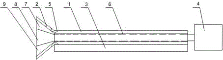
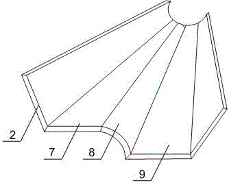
[0022] Such as Figure 1 to Figure 3 As shown, the steel pipe cutting waste liquid collection method of the present invention includes the following steps. After the steel pipe is cut, it is pushed out from the cutting space to the pipe groove 1. The rotation of the motor 4 drives the pipe groove 1 to rotate on the support shaft 6. The steel pipe follows the pipe groove 1. Rotate together, and finally stacked on the transport equipment near the cutting machine; during the process of pushing back and rotating the pipe groove 1, the residual coolant and debris in the steel pipe will flow out automatically, and the outflowing debris mixture passes through the collection groove 2 The upper horizontal surface 7 slowly flows into the inclined surface 9 under the buffer of the transitional arc surface 8, and finally the debris mixture flows from the inclined surface 9 into the waste pool below the cutting machine, which is intensively processed by the operator; when the steel pipe fal...

Embodiment 2

[0025] Such as figure 1 and figure 2 As shown, in this embodiment, on the basis of Embodiment 1, a baffle plate 3 is obliquely arranged on one side of the pipe groove 1, and the angle between the baffle plate 3 and the pipe groove 1 is 115°~135° °; also includes a protective pad 5, the protective pad 5 is installed at the junction of the pipe groove 1 and the collection tank 2. When the pipe groove 1 rotates, the steel pipe in the groove falls directly, which is easy to collide with the ground and cause the surface of the steel pipe to be sunken; The angle between them is 115°~135°, which can buffer the falling steel pipe due to rotation, reduce the kinetic energy of the steel pipe before falling, and avoid damage to the steel pipe; after the steel pipe is cut, it is pushed into the pipe groove 1, and the pipe groove 1 The connection between the collection tank 2 and the outer surface of the steel pipe is likely to rub against the outer surface of the steel pipe, thereby ca...


PUM


Abstract

The invention discloses a collection method for waste cutting fluid of steel pipes. A special-shaped collection tank can collect a scrap mixture completely. The inner horizontal plane of the collection tank and the bottom of a pipe groove are kept on the same height so that when the pipe groove rotates, the scrap mixture in the pipes can be smoothly discharged. Through treatment of the transition arc surface and the inclined surface, the scrap mixture will not splash in the collection tank and can flow out of the collection tank fast and stably, cooling fluid and scraps left in the pipes after the steel pipes are cut can be conveniently cleared away, and the cleanliness and tidiness of the operating environment in a cutting workshop can be guaranteed.

Description

technical field [0001] The invention relates to a cutting machine, in particular to a method for collecting steel pipe cutting waste liquid. Background technique [0002] Seamless steel pipe is a long strip of steel with a hollow section and no seams around it. The steel pipe has a hollow cross-section and is widely used as a pipeline for transporting fluids, such as pipelines for transporting oil, natural gas, gas, water and certain solid materials. Compared with solid steel such as round steel, the steel pipe is lighter in weight when the bending and torsional strength is the same. It is an economical cross-section steel and is widely used in the manufacture of structural parts and mechanical parts, such as oil drill pipes, automobile transmission shafts, and bicycles. Frames and steel scaffolding used in building construction, etc. The use of steel pipes to manufacture ring parts can improve the utilization rate of materials, simplify the manufacturing process, save ma...

Claims


Application Information

Patent Timeline
IPC IPC(8): B23Q11/00
CPCB23Q11/10
Inventor 吴光武
Owner CHENGDU XINGBODA PRECISION MACHINERY
Why Eureka
Try Eureka