A kind of automatic cleaning mechanism for drilling bit and using method

A drilling bit, automatic cleaning technology, applied in the direction of drilling equipment, drilling tools, dryers, etc., can solve the problems of bit corrosion, drilling bit fixation, inability to quickly dry the drilling bit, etc., to achieve convenient clamping and removal, lifting Good stability and fixing effect

Active Publication Date: 2021-11-09
东营辰鑫应用技术开发有限公司
View PDF6 Cites 0 Cited by
  • Summary
  • Abstract
  • Description
  • Claims
  • Application Information

AI Technical Summary

Problems solved by technology

[0006] The object of the present invention is to provide an automatic cleaning mechanism for a drilling bit. By setting a rotating clamping assembly and a reciprocating cleaning assembly, not only the drilling bit can be effectively fixed to ensure the stability of the cleaning process, but also the drilling bit can be automatically rotated and cleaned. The transverse reciprocating motion of the annular brush helps to clean the entire surface of the drilling bit, and by combining brushing and spraying, the surface of the drilling bit is cleaned, which significantly improves the cleaning effect and cleaning efficiency. Combining the cleaning and drying functions, the drilling bit is automatically dried after cleaning, which significantly improves the overall use effect of the cleaning mechanism, and solves the problem that the existing cleaning mechanism cannot fix the drilling bit, and the drilling needs to be manually fixed during the cleaning process. Drill bit, and in the process of cleaning, it is necessary to manually turn over the drilling bit to clean the entire outer surface of the drilling bit, and the cleaned drilling bit cannot be dried quickly, and the aqueous solution carried on the drilling bit is likely to cause the problem of drill bit corrosion

Method used


Image

  • A kind of automatic cleaning mechanism for drilling bit and using method
  • A kind of automatic cleaning mechanism for drilling bit and using method
  • A kind of automatic cleaning mechanism for drilling bit and using method

Examples


Embodiment 1

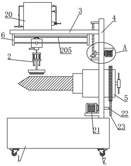
[0053] Such as Figure 1-8 As shown, the automatic cleaning mechanism for a drilling bit proposed by the present invention includes a base 1, a horizontal plate 3, a vertical plate 4 and a walking wheel 7, the top of the base 1 is fixed with a vertical plate 4 by bolts, and the bottom of the base 1 is installed There are multiple sets of walking wheels 7, through which the handling and movement of the equipment is convenient. The horizontal plate 3 is horizontally arranged above the base 1 and connected with the vertical plate 4. The vertical plate 4 is equipped with a rotating clamping assembly 5, and the rotating clamp The tightening assembly 5 is used to clamp the drilling bit, which helps to improve the stability of the drilling bit cleaning process, and the reciprocating cleaning assembly 2 is installed under the horizontal plate 3;

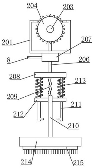
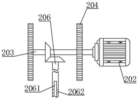
[0054] The reciprocating cleaning assembly 2 includes a movable box 201, a first motor 202, a first output shaft 203, a first gear 204, a r...

Embodiment 2

[0059] Such as figure 1 and Figure 9 As shown, the difference between this embodiment and Embodiment 1 is that the top of the horizontal plate 3 is fixed with a fixed box 20 by bolts, and the fixed box 20 is provided with a water storage chamber 11 and a heating chamber 12, and the heating chamber 12 is located in the water storage chamber. Above the chamber 11, cleaning water is stored in the water storage chamber 11, and a water inlet pipe is installed on the water storage chamber 11. The water inlet pipe is used to add cleaning water to the water storage chamber 11, and the heating chamber 12 is used to heat the input air. The top of the heating chamber 12 is fixed with multiple sets of first partitions 18 by bolts, and there is a gap between the first partitions 18 and the bottom of the heating chamber 12, and the bottom of the heating chamber 12 is fixed with multiple sets of second partitions by bolts. plate 19, and the second partition 19 is provided with a gap with t...

Embodiment 3

[0063] Such as figure 1 and Figure 10 As shown, the difference between this embodiment and Embodiment 1 and Embodiment 2 is that the horizontal plate 3 is slidably connected with the vertical plate 4 through slide rails, the horizontal plate 3 can slide vertically along the vertical plate 4, and the vertical plate 4 Upper and lower two groups of second mounts 29 are installed, the horizontal plate 3 is located between the two groups of second mounts 29, and the second screw rod 30 is installed in rotation between the two groups of second mounts 29, and the second screw rod 30 is vertical. Vertically arranged and screwed with the horizontal plate 3, the vertical plate 4 is fixedly installed with the third motor 27 through the motor base, the output end of the third motor 27 is equipped with the third output shaft 28, the third motor 27 is used to drive the third output shaft 28, and the other end of the third output shaft 28 is connected to the second screw rod 30 through a b...


PUM


Abstract

The invention relates to the technical field of drilling tools, and is used to solve the problem that the existing cleaning mechanism cannot fix the drilling bit, the drilling bit needs to be manually turned over during the cleaning process, and the cleaned drilling bit cannot be quickly dried. The problem that the effect needs to be improved is specifically an automatic cleaning mechanism for drilling bits and its use method, including a base, a vertical plate is installed on the top of the base, a horizontal plate is connected with the vertical plate, and a rotating clamping assembly is installed on the vertical plate; the present invention The stability of the cleaning process is ensured by the set of rotating clamping components and reciprocating cleaning components, and the drilling bit can be automatically rotated and the annular brush can be reciprocated laterally, which helps to clean the entire surface of the drilling bit. The surface of the drilling bit is cleaned by combining brushing and spraying, and the overall use effect of the cleaning mechanism is significantly improved by combining the cleaning and drying functions.

Description

technical field [0001] The invention relates to the technical field of drilling tools, in particular to an automatic cleaning mechanism for drilling bits and a use method thereof. Background technique [0002] Drilling equipment, in a broad sense, includes a complete set of ground equipment for drilling, special drilling tools and drilling instruments. Drilling equipment is divided into rotation, lifting, circulation, power and transmission, control and other systems according to functions. Drilling bits belong to drilling equipment. Partly, the drill bit in the drilling equipment is very important. The drill bit needs to be cleaned after use to remove the soil on the surface of the drill bit, so as to prevent the material on the surface of the drill bit from corroding its surface and causing damage to the drill bit; [0003] In the Chinese patent application number 2017206118858, a cleaning device for drilling equipment is disclosed, which includes a bracket. The lower end ...

Claims


Application Information

Patent Timeline
Patent Type & Authority Patents(China)
IPC IPC(8): E21B12/06F26B21/00
CPCE21B12/06F26B21/00
Inventor 王平
Owner 东营辰鑫应用技术开发有限公司
Why Eureka
Try Eureka