Waterproof structure
A waterproof structure, rotating shaft technology, applied in the direction of engine sealing, engine components, mechanical equipment, etc., can solve the problem of elongated outflow path, etc., to achieve the effect of improving waterproof performance
- Summary
- Abstract
- Description
- Claims
- Application Information
AI Technical Summary
Problems solved by technology
Method used
Image
Examples
Embodiment 1
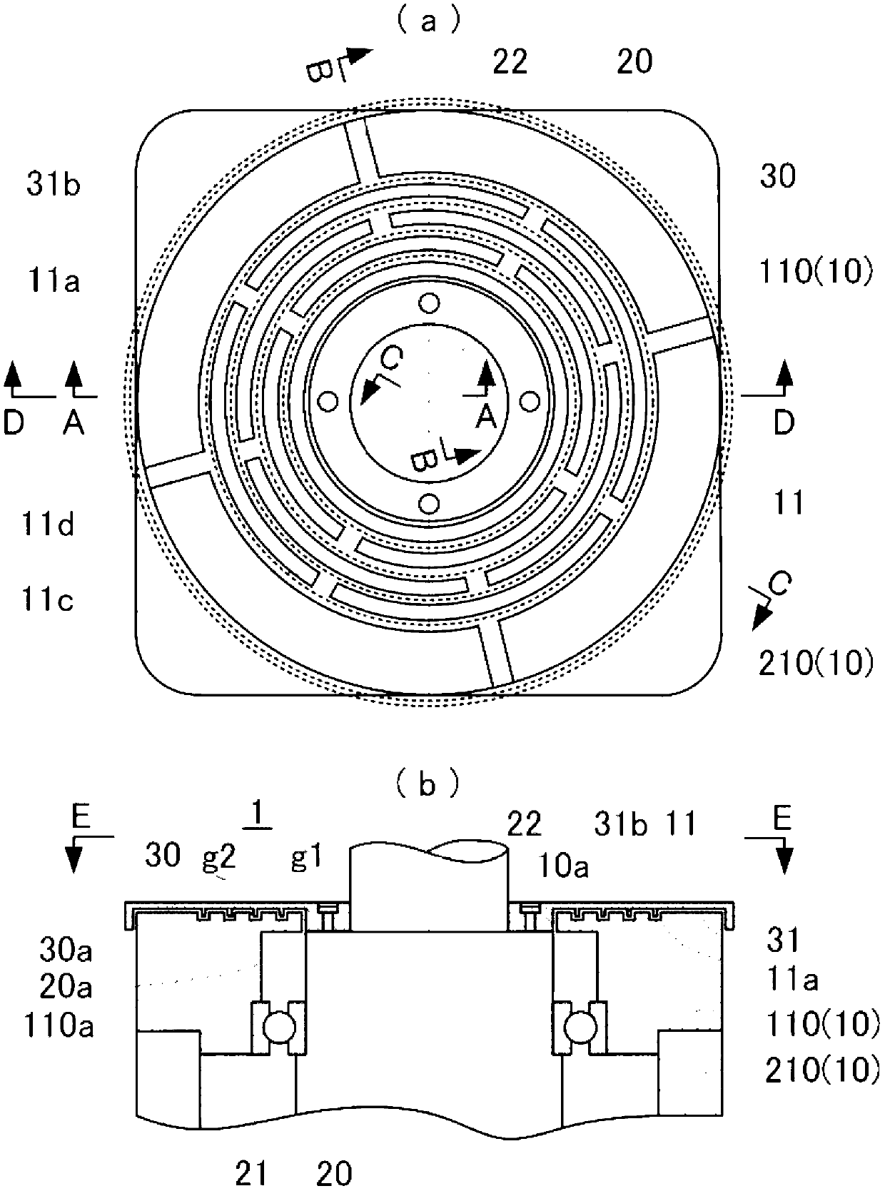
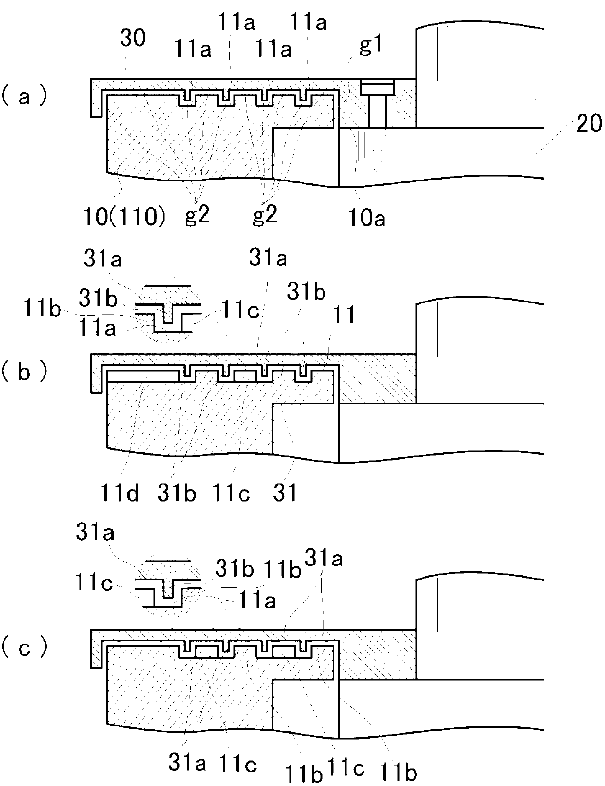
[0033] figure 1 Showing the waterproof structure of the rotating shaft penetration part related to Example 1, an annular recess is formed on the housing, an annular protrusion is formed on the flange, and an annular recess is formed to connect the annular recesses to each other. The structure of the connected part of the connection, figure 1 (a) shows a view viewed from the outside of the casing along the axial direction of the rotating shaft, wherein the flange portion is indicated by a dotted line, figure 1 (a) for figure 1 (b) The top view of the E-E direction, figure 1 (b) for figure 1 (a) Cross-sectional view along line D-D.
[0034] The waterproof structure of the rotating shaft penetration part related to Embodiment 1 includes: a casing 10, a through hole 10a provided on the casing 10, a rotating shaft 20 rotatably inserted in the through hole 10a, and a casing 10 outside. The flange portion 30 is fixed to the rotating shaft 20 and rotates together. In this waterp...
Embodiment 2
[0060] The waterproof structure of the rotating shaft penetration portion related to the second embodiment basically has the same configuration and effects as those of the above-mentioned first embodiment. For this reason, the description of the points that are the same as in the first embodiment is omitted. Hereinafter, the configuration and effects unique to the second embodiment will be described.
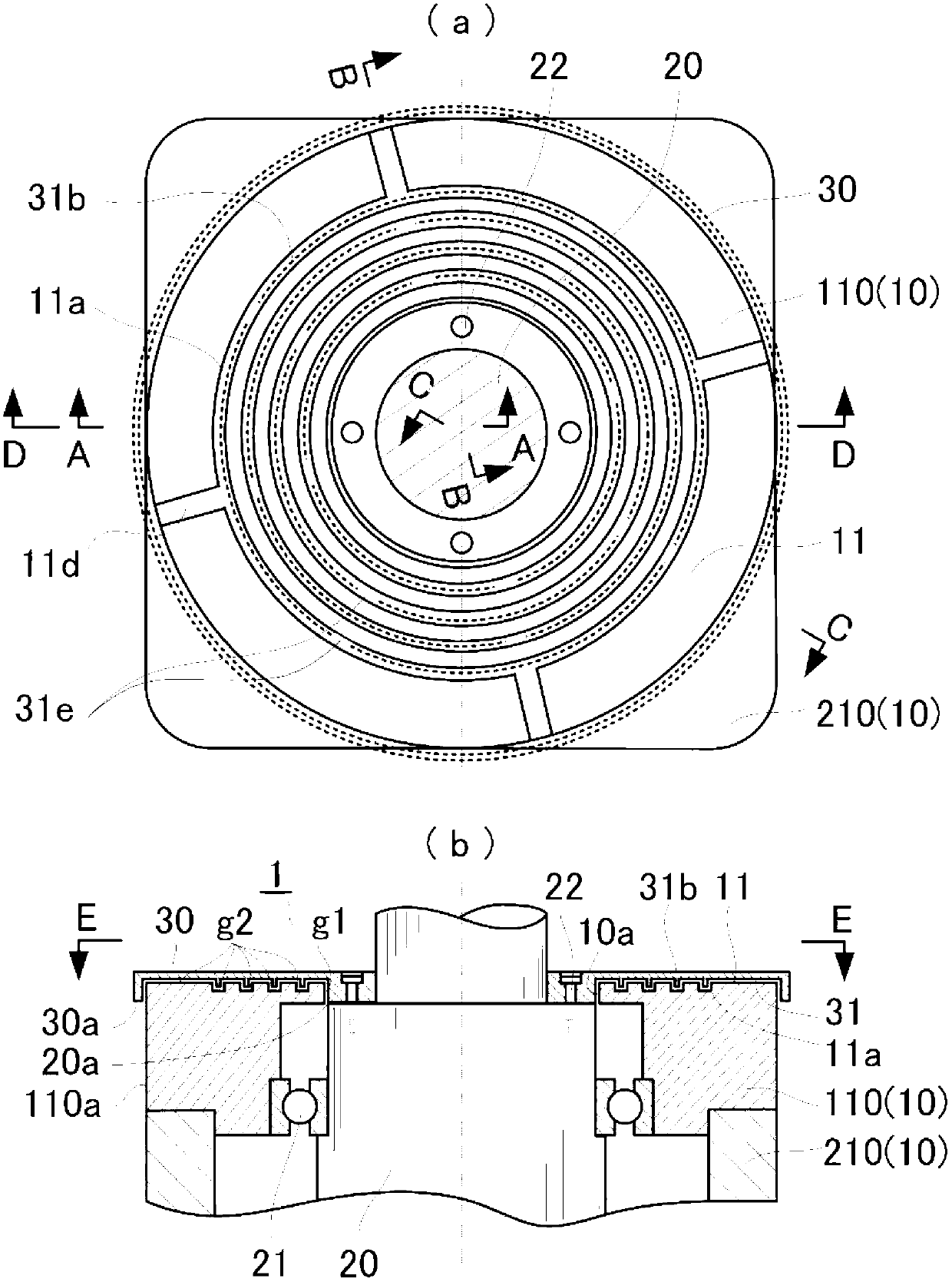
[0061] image 3 Showing the waterproof structure of the rotating shaft penetration part related to Example 2, an annular concave portion is formed on the casing, an annular convex portion is formed on the flange portion, and a notch is formed on the annular convex portion. The structure of the connected part constituted by the part, image 3 (a) shows a view viewed from the outside of the casing along the axial direction of the rotating shaft, wherein the flange portion is indicated by a dotted line, image 3 (a) for image 3 (b) The top view of the E-E direction, image 3 ...
Embodiment 3
[0067] The waterproof structure of the rotating shaft penetration portion related to the third embodiment basically has the same configuration and effects as those of the above-mentioned first embodiment. For this reason, the description of the points that are the same as in the first embodiment is omitted. Hereinafter, the configuration and effects unique to Embodiment 3 will be described.
[0068] Figure 5 Showing the waterproof structure of the rotating shaft penetrating part related to Example 3, an annular convex portion is formed on the housing, an annular concave portion is formed on the flange portion, and an annular concave portion is formed that can The structure of interconnected connected parts, Figure 5 (a) shows a view viewed from the outside of the casing along the axial direction of the rotating shaft, wherein the flange portion is indicated by a dotted line, Figure 5 (a) for Figure 5 (b) The top view of the E-E direction, Figure 5 (b) for Figure 5 ...
PUM
 Abstract
Description
Claims
Application Information
 - R&D
- Intellectual Property
- Life Sciences
- Materials
- Tech Scout
- Unparalleled Data Quality
- Higher Quality Content
- 60% Fewer Hallucinations
Browse by: Latest US Patents, China's latest patents, Technical Efficacy Thesaurus, Application Domain, Technology Topic, Popular Technical Reports.
© 2025 PatSnap. All rights reserved.Legal|Privacy policy|Modern Slavery Act Transparency Statement|Sitemap|About US| Contact US: help@patsnap.com


