Connector and production method

A connector and abutment surface technology, which is applied in the direction of vehicle connectors, connections, conductive connections, etc., can solve problems such as corrosion, and achieve the effects of improving moldability, moldability, and good sealing

Inactive Publication Date: 2012-07-11
HITACHI ASTEMO LTD
View PDF7 Cites 15 Cited by
  • Summary
  • Abstract
  • Description
  • Claims
  • Application Information

AI Technical Summary

Problems solved by technology

In order to make an electrical connection, there should be an exposed portion on the covered wire where the internal lead must be exposed. However, if moisture from the outside enters the exposed portion, the moisture will cause corrosion.

Method used


Image

  • Connector and production method
  • Connector and production method
  • Connector and production method

Examples


Embodiment 1

[0083] [Configuration of Embodiment 1]

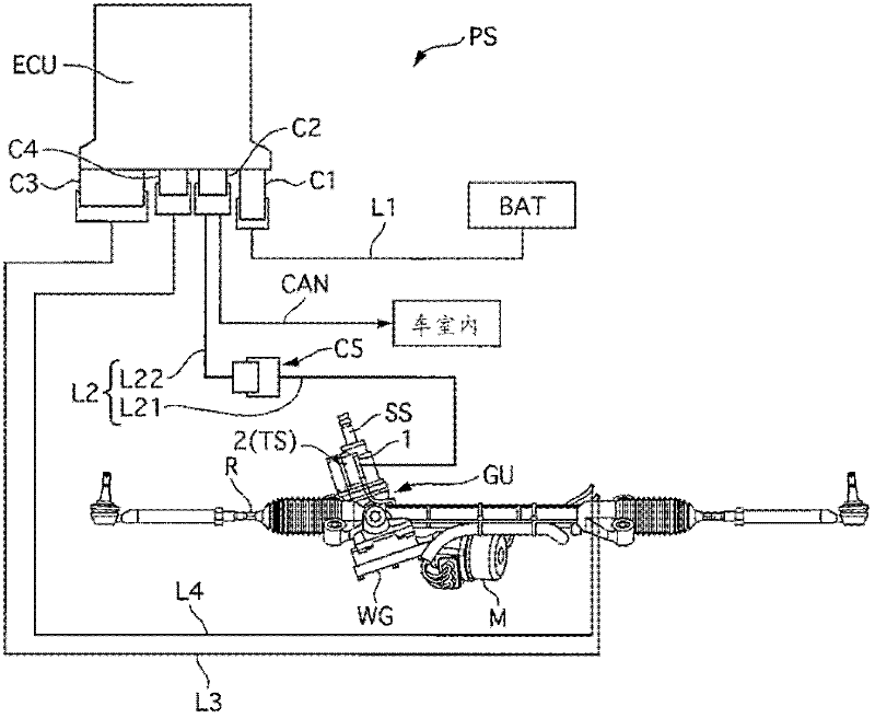
[0084]The connector 1 of the first embodiment is installed in an electric power steering device (hereinafter referred to as "device PS") of an automobile. It should be noted that the connector of the present invention and its manufacturing method can also be applied to devices other than the electric power steering system PS, and mounted on devices other than automobiles. figure 1 It is a system configuration diagram of the device PS provided with the connector 1 . The device PS has a gear unit GU (power steering gear unit) as an actuator and a control unit ECU as a control device. The connector 1 is provided on the gear unit GU, and electrically connects the outside and the inside of the gear unit GU.

[0085] The gear unit GU has a motor M as a motor, a worm gear WG as a reduction mechanism, and a torque sensor TS as steering torque detection means. The driving force of the motor M is transmitted to the worm R via the worm gear WG,...

Embodiment 2

[0156] The connector 1 of the second embodiment differs from the first embodiment in the shape of the wall portion 310 (recess 316 ) of the second molded part 31 . Figure 15 is the connector 1 and Figure 7 Same main view. In addition, illustration of the bolt penetration hole 319 etc. is abbreviate|omitted. like Figure 15 As shown, the annular wall portion 310 is formed within a predetermined range of the circumferential direction of the first molding part 30, specifically on both sides of the z-axis direction of the first molding part 30, from the first molding part 30 The outer peripheral surface is spaced apart and formed to adjoin (close to) the first mold member 30 in a portion other than a predetermined range in the above-mentioned circumferential direction, specifically, on both sides in the y-axis direction of the first mold member 30 . That is, the portions on both sides in the y-axis direction of the wall portion 310 are provided on the inner peripheral side th...

Embodiment 3

[0162] The connector 1 of Embodiment 3 is different from Embodiment 1 in the shape of the wall portion 310 (recess 316 ) of the second molded part 31 . Figure 16 is the connector 1 of Example 3 with Image 6 The same partial cross-sectional view only shows the part on the negative side of the y-axis. In addition, illustration of the seal groove 318, the pin 31b, etc. is abbreviate|omitted. like Figure 16 As shown, the second molding member 31 makes the inner peripheral surface of the wall portion 310 closer (on the inner peripheral side) to the positive x-axis side (the side of the bottom surface 315 ) from the negative x-axis direction side (opening side) The form of the first molding part 30 is formed in an inclined shape. In other words, a conical portion T is provided on the inner peripheral surface of the concave portion 316 for accommodating the adhesive 32 so that the dimension in the y-axis direction (inner diameter) becomes smaller toward the bottom in the positi...


PUM


Abstract

The present invention relates to a connector and a production method. The connector has a simple structure and maintains good waterproof characteristics. The connector has a molding unit (30) and a sealing unit (32). The molding unit is formed by that the uncovered portions (B) of covered wires (10a-10e) project on the x positive side from a first end of the molding unit and the covered portions (A) of covered wires (10a-10e) project on the x negative side from a second end of the molding unit, and thereby holding the conducting lines to fix positions of the conducting lines relative to one another. The sealing member of an adhesive (32) adheres to the second end of the molding unit (30) on the x negative side and adheres to the outer circumferential surface of the insulating covering of the covered segment of each covered wire (10a-10e) .

Description

technical field [0001] The present invention relates to connectors. Background technique [0002] Conventionally, a connector (terminal structure) for electrically connecting a plurality of devices has been known. For example, an electric power steering device disclosed in the following Patent Document 1 has a signal connector open to the outside, and a signal line for transmitting and receiving electric signals with a vehicle is connected to the signal connector. Usually, the signal line is composed of a covered wire in which a conductive wire is covered with a waterproof insulator. In order to perform electrical connection, there should be an exposed portion on the covered wire where the internal lead wire must be exposed. However, if moisture from the outside enters the exposed portion, the moisture will cause corrosion. Therefore, various waterproof structures have been adopted in which moisture does not penetrate into the exposed part, but a structure that can obtain ...

Claims


Application Information

Patent Timeline
Patent Type & Authority Applications(China)
IPC IPC(8): H01R13/502H01R13/52H01R24/00H01R43/00
CPCH01R13/5202H01R43/24H01R9/03H01R13/504H01R2201/26
Inventor 大西辉幸矶部晋一椎野高太郎高桥哲
Owner HITACHI ASTEMO LTD
Why Eureka
Try Eureka