Aquaculture turn-scoop-type wave generator

A technology for aquaculture and generators, applied in the fields of application, fish farming, climate change adaptation, etc., can solve problems such as poor efficiency, low energy conversion efficiency, and waste of electric energy, so as to promote uniform distribution, reduce farming costs, and improve farming effect of effectiveness

Inactive Publication Date: 2014-11-26
CHANG JUNG CHRISTIAN UNIV
View PDF11 Cites 0 Cited by
  • Summary
  • Abstract
  • Description
  • Claims
  • Application Information

AI Technical Summary

Problems solved by technology

[0002] Most of the existing aeration equipment used in aquaculture is designed for high speed. For example, the common impeller-type water wheel aerator mainly uses the high-speed rotation of the flat blade to slap the water surface to generate water splashes and water flow, and uses water spray to increase water and air. The contact area, but because the water flow generated is not large, it is difficult to take away the water body with high dissolved oxygen immediately, so that some water splashes fall into the water and are kicked up again, resulting in a waste of electric energy
Furthermore, because the water pumping range of the water wheel aerator is only limited to the vicinity of the water surface where the amount of dissolved oxygen is already high, after fetching water, the dissolved oxygen is mainly diffused to the depth of the pool through diffusion, which is a kind of Relatively slow process with poor efficiency
[0003] In addition, the high-speed design of the aeration equipment and the way it converts electrical energy into fluid mechanical energy have disadvantages such as low energy conversion efficiency, energy concentration in a small amount of water, lack of large-scale convection mechanism, and uneven distribution of dissolved oxygen, so that it is applied to larger In large-scale outdoor aquaculture ponds, it is often necessary to win by quantity, which makes the aeration equipment purchase cost and power consumption cost of the aquaculture industry remain high

Method used


Image

  • Aquaculture turn-scoop-type wave generator
  • Aquaculture turn-scoop-type wave generator
  • Aquaculture turn-scoop-type wave generator

Examples


Embodiment Construction

[0022] The present invention will be described in detail below in conjunction with the accompanying drawings and embodiments.

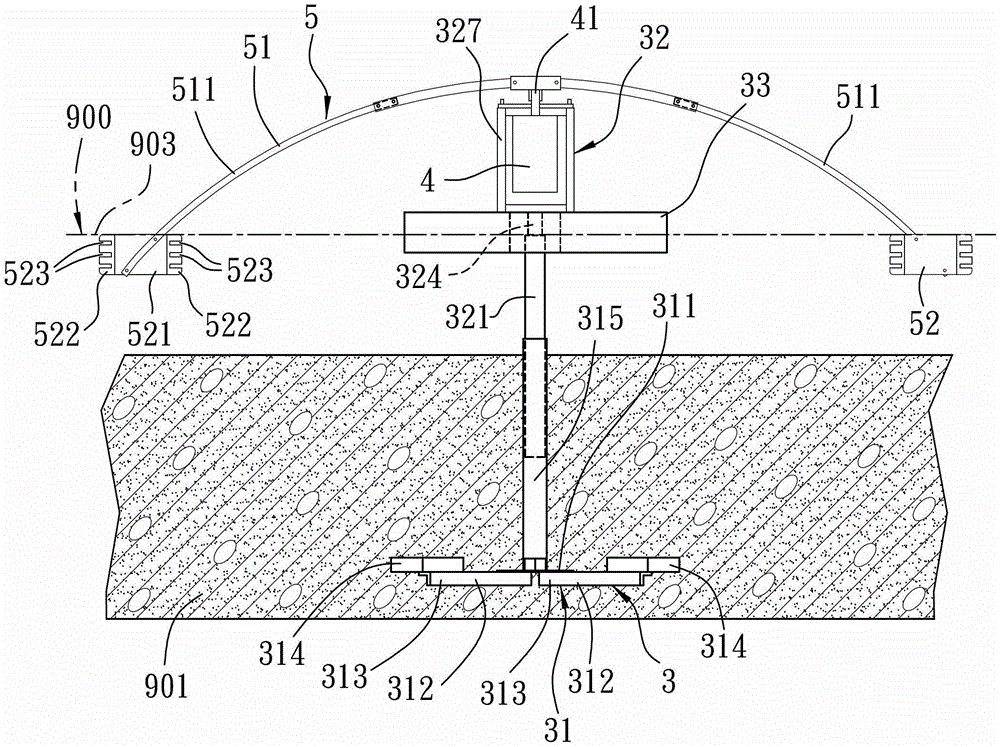
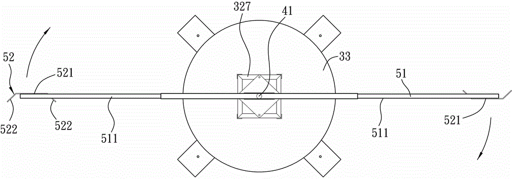
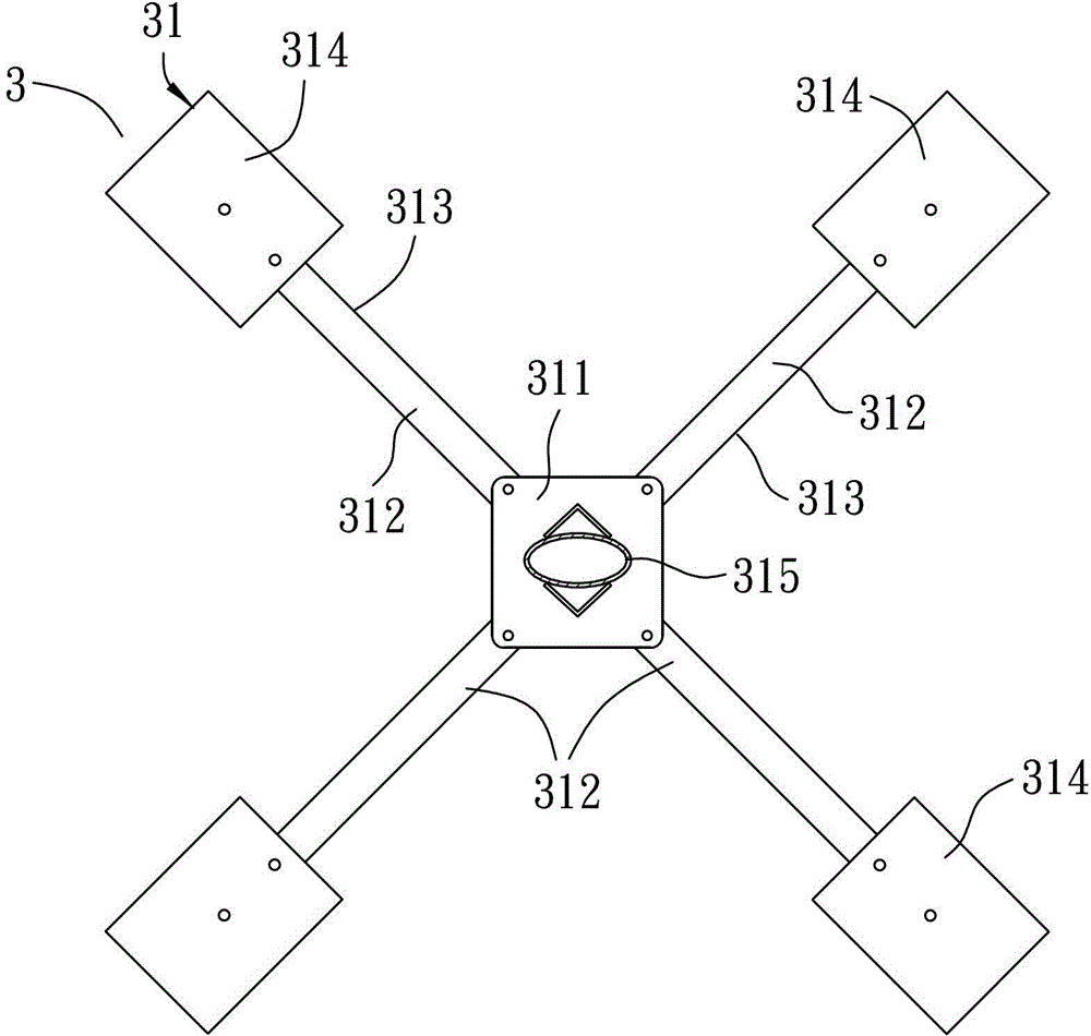
[0023] Such as figure 1 , 2 As shown, the preferred embodiment of the rotary dipper type water wave generator for aquaculture of the present invention is suitable for being installed in a culture pond 900, and piled on the pond bottom soil layer 901 at the bottom of the culture pond 900, and can be used to promote cultivation The pool water in the pool produces currents and waves.

[0024] The aquaculture rotating dipper type water wave generator includes a floating support mechanism 3 fixed on the bottom soil layer 901 and extending upwards out of the pool surface 903, and a floating support mechanism 3 fixed on the floating support mechanism 3 and located on the pond surface of the aquaculture pond. The reduction motor 4 above 903, and a water wave generating mechanism 5 installed on the reduction motor 4 and extending under the pool surface 903 f...


PUM


Abstract

An aquaculture turn-scoop-type wave generator includes a floating bracket body, a gear motor and a wave generating mechanism. The floating bracket includes a base buried in bottom soil of a pool, a telescopic rack mounted on the base and being adjustable in length for arranging the gear motor, and a buoying device floating on the surface of the pool. The wave generating mechanism comprises a rotating arm fixed on the gear motor and two webs driven by the rotating arm to push water. The aquaculture turn-scoop-type wave generator with the structural design can generate large flows of water, large-size vortex and large-scale waves, can quickly promote uniform distribution of dissolved oxygen, and can improve breeding effectiveness and reduce breeding costs because current flow range is much larger than a normal waterwheel aerator.

Description

technical field [0001] The invention relates to a water wave generator, in particular to a scoop-type water wave generator for aquaculture. Background technique [0002] Most of the existing aeration equipment used in aquaculture is designed for high speed. For example, the common impeller-type water wheel aerator mainly uses the high-speed rotation of the flat blade to slap the water surface to generate water splashes and water flow, and uses water spray to increase water and air. However, because the generated water flow is not large, it is difficult to take away the water body with high dissolved oxygen immediately, so that some water splashes fall into the water and are kicked up again, resulting in a waste of electric energy. Furthermore, because the water pumping range of the water wheel aerator is only limited to the vicinity of the water surface where the amount of dissolved oxygen is already high, after fetching water, the dissolved oxygen is mainly diffused to the ...

Claims


Application Information

Patent Timeline
Patent Type & Authority Patents(China)
IPC IPC(8): A01K63/04
CPCY02A40/81
Inventor 吴俊概
Owner CHANG JUNG CHRISTIAN UNIV
Why Eureka
Try Eureka