Lifting trolley

A trolley and base technology, which is applied in the direction of the trolley’s crane, load block, load suspension components, etc., can solve the problems of time-consuming, laborious, safety hazards, etc., and achieve the effect of convenient use and labor saving

Inactive Publication Date: 2013-09-11
江苏天翔电气有限公司
View PDF6 Cites 3 Cited by
  • Summary
  • Abstract
  • Description
  • Claims
  • Application Information

AI Technical Summary

Problems solved by technology

When the mass of the parts is large, manual handling is not only time-consuming and laborious, but also has certain safety hazards

Method used


Image

  • Lifting trolley
  • Lifting trolley
  • Lifting trolley

Examples


Embodiment Construction

[0016] Specific embodiments of the present invention will be described in detail below in conjunction with the accompanying drawings.

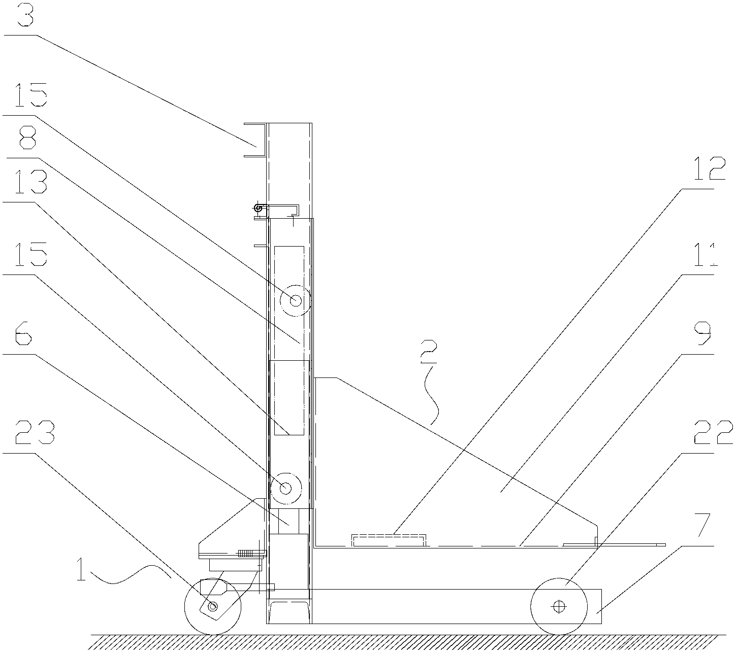
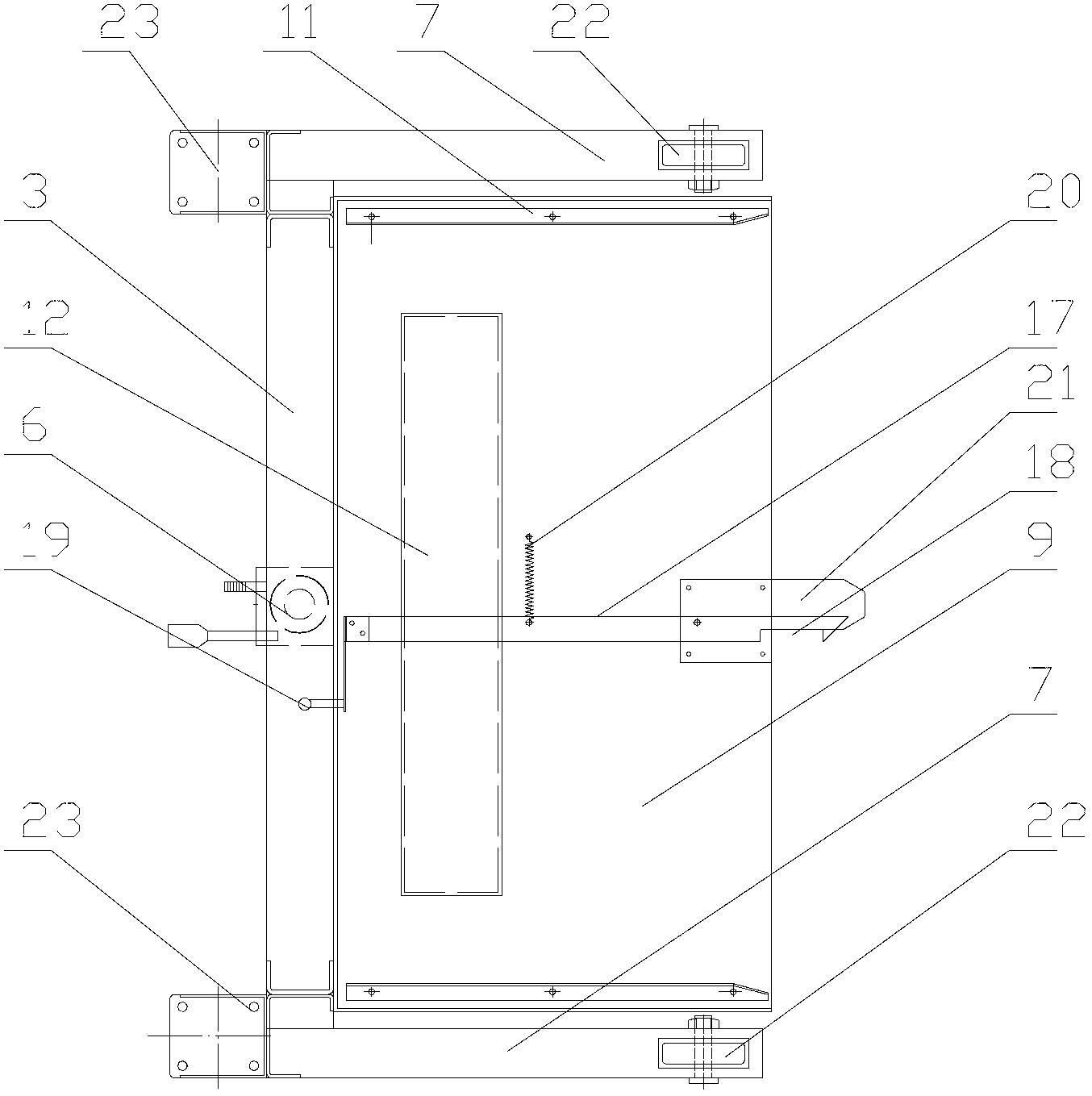
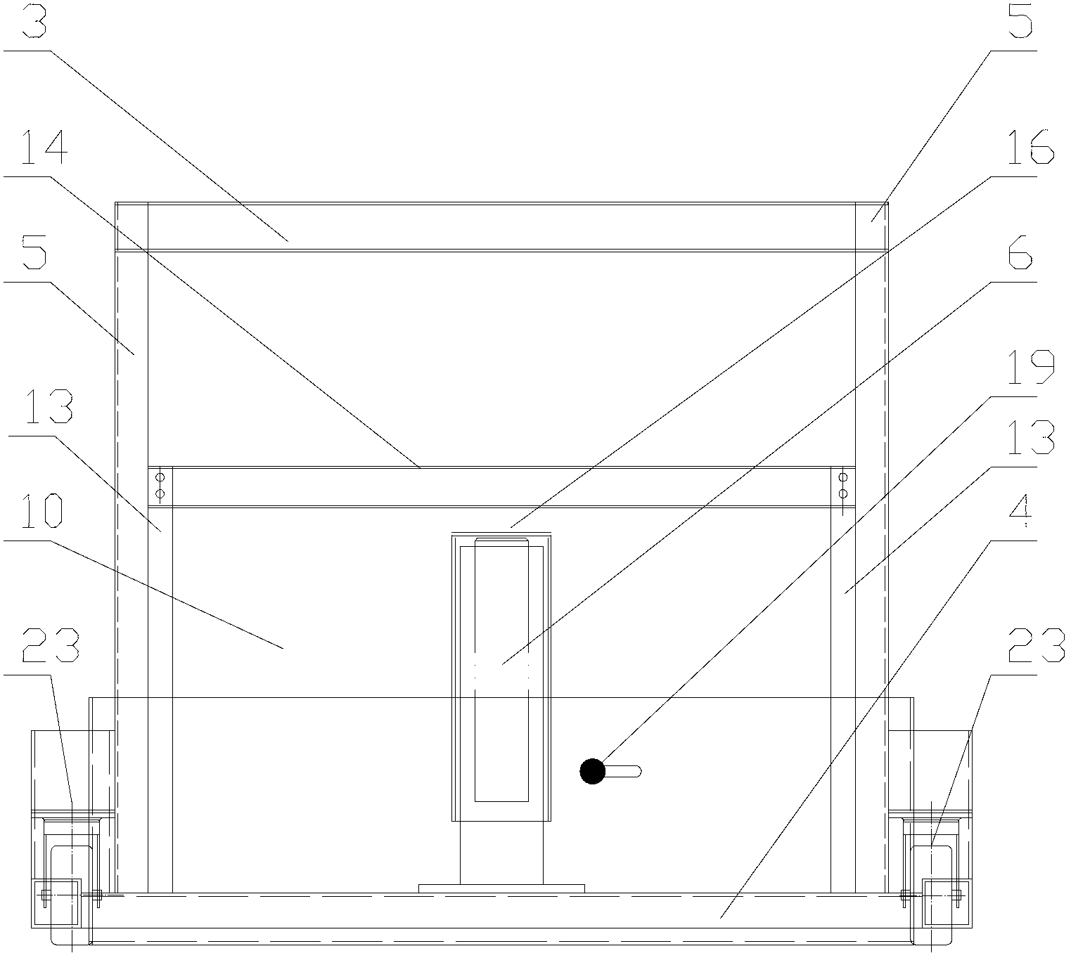
[0017] Such as figure 2 As shown, a lifting trolley includes a base 1 and a lifting seat 2 movably arranged on the base 1. The base 1 includes a top beam 3, a bottom beam 4 and two columns 5 arranged between them. , the bottom beam 4 is provided with a jack 6, the two ends of the bottom beam 4 are respectively vertically provided with a forward beam 7, and the opposite surfaces of the two columns 5 are respectively provided with a chute 8, and the lifting seat 2 is movably arranged on the chute 8 , the lifting seat 2 includes a base plate 9 , a back plate 10 vertically arranged on the base plate 9 , and two side plates 11 connecting the base plate 9 and the back plate 10 . The bottom plate 9 is provided with reinforcing ribs 12 . Mounting columns 13 are respectively provided at both ends of the backboard 10 , and connecting beams 14 are pro...


PUM


Abstract

The invention discloses a lifting trolley. The lifting trolley comprises a base and a lifting base arranged on the base in a moving manner, wherein the base is provided with idler wheels; the base comprises a top cross beam, a bottom cross beam and two stand columns arranged between the top cross beam and the bottom cross beam, and the bottom cross beam is provided with a jack; each of the two ends of the bottom cross beam is vertically provided with a front stretching beam, each of the opposite surfaces of the two stand columns is provided with a chute, and the lifting base is arranged in the chutes in the moving manner, and the lifting base comprises a bottom plate, a back plate vertically arranged on the bottom plate, as well as two side plates connected with the bottom plate and the back plate; the end part on each of the two sides of the back plate is provided with a mounting column, the outer side faces of the mounting columns are provided with pulleys, the pulleys are clamped in the chutes arranged in the stand columns, and a pushing plate is horizontally arranged on the back plate and above the jack. The lifting trolley has the advantages that the cargo is safely convenient to carry and lift.

Description

technical field [0001] The invention relates to a lifting trolley. Background technique [0002] When enterprises install equipment, workers often carry it manually to install certain components at a certain height. When the mass of the parts is large, manual handling is not only time-consuming and laborious, but also has certain safety hazards. Contents of the invention [0003] The technical problem to be solved by the present invention is to provide a lifting trolley which is safe and convenient for carrying and lifting goods. [0004] In order to solve the above technical problems, the technical solution adopted in the present invention is: a lifting trolley, including a base and a lifting seat movably arranged on the base, rollers are arranged on the base, and the base includes a top beam , the bottom beam and the two columns between them, the bottom beam is provided with a jack, the two ends of the bottom beam are respectively vertically provided with front extensi...

Claims


Application Information

Patent Timeline
IPC IPC(8): B66C19/00B66C11/00
Inventor 钟杰蒋建兴
Owner 江苏天翔电气有限公司
Why Eureka
Try Eureka