Driving circuit of electromagnetic valve
A driving circuit and solenoid valve technology, which is applied in the direction of engine components, machines/engines, mechanical equipment, etc., can solve the problems of unable to meet the requirements of the driving current of the solenoid valve, large current fluctuations, etc., and achieve a stable driving current and satisfy the driving current. required effect
- Summary
- Abstract
- Description
- Claims
- Application Information
AI Technical Summary
Problems solved by technology
Method used
Image
Examples
Embodiment 1
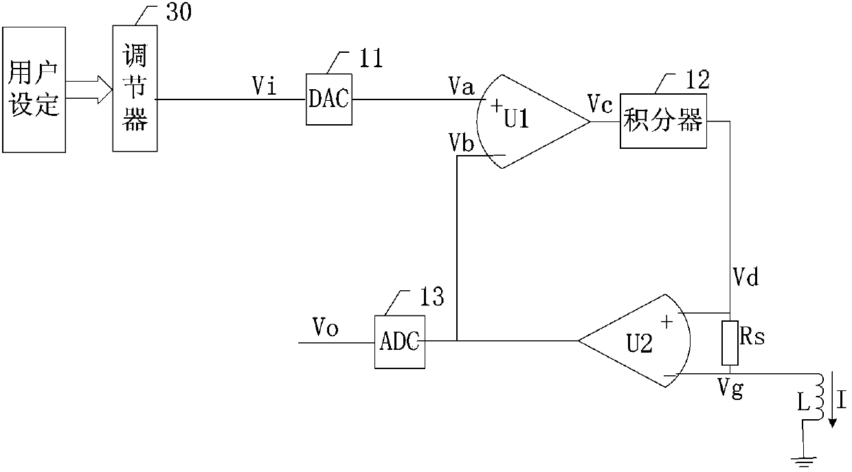
[0035] figure 1 It is a structural diagram of a solenoid valve driving circuit disclosed in the embodiment of the present application;
[0036] Such as figure 1 The solenoid valve driving circuit shown includes: a regulator 30, a digital-to-analog conversion circuit 11, a first differential amplifier U1, a second differential amplifier U2, an integrator 12, a sampling resistor Rs and an analog-to-digital conversion circuit 13, wherein:
[0037] The output end of the regulator 30 is connected with the input end of the digital-analog conversion circuit 11; the output end of the digital-analog conversion circuit 11 is connected with the non-inverting input end of the first differential amplifier U1; the output end of the first differential amplifier U1 is connected with the integral The input terminal of the device 12 is connected; the output terminal of the integrator 12 is connected with the non-inverting input terminal of the second differential amplifier U2; the output termi...
Embodiment 2
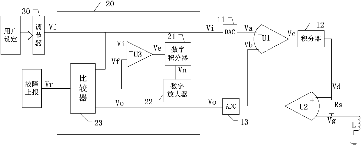
[0051] figure 1 It is a structural diagram of another driving circuit disclosed in the embodiment of the present application;
[0052] In this embodiment, a monitoring circuit is added on the basis of the driving circuit provided in the first embodiment, and the feedback signal is used as the signal to be detected by the monitoring circuit.
[0053] Such as figure 1 As shown, the increased monitoring circuit includes: digital subtractor U3, digital integrator 21, digital amplifier 22, comparison circuit 23, wherein:
[0054] The digital subtractor U3, the digital integrator 21 and the digital amplifier 22 form an inertial analog circuit, which is used to simulate the inertial characteristics of the driving circuit, and is used to simulate the inertial characteristics of the solenoid valve driving circuit. The time constant of the digital inertial circuit is set to be greater than that of the solenoid valve driving circuit. The time constant of the circuit.
[0055] The posi...
PUM
 Abstract
Description
Claims
Application Information
 - R&D
- Intellectual Property
- Life Sciences
- Materials
- Tech Scout
- Unparalleled Data Quality
- Higher Quality Content
- 60% Fewer Hallucinations
Browse by: Latest US Patents, China's latest patents, Technical Efficacy Thesaurus, Application Domain, Technology Topic, Popular Technical Reports.
© 2025 PatSnap. All rights reserved.Legal|Privacy policy|Modern Slavery Act Transparency Statement|Sitemap|About US| Contact US: help@patsnap.com


