
Control system used for automatic start-close type bath heater
A control system, open and close technology, applied in the electronic field, can solve the problems of unstable output drive current, unable to control the temperature of Yuba, etc., to achieve the effect of ensuring stability, prolonging service life, and maintaining stable current
- Summary
- Abstract
- Description
- Claims
- Application Information
AI Technical Summary
Problems solved by technology
Method used
Image

Examples
Embodiment
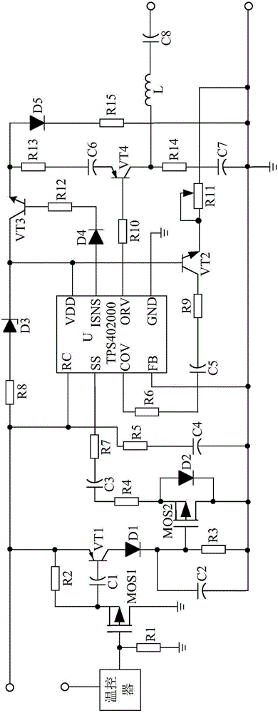
[0016] Such as figure 1 As shown, the present invention mainly consists of a control chip U, a temperature controller, a triode VT2, a resistor R5, a resistor R6, a resistor R8, a resistor R9, a polar capacitor C4, a polar capacitor C5, a Zener diode D3, and a transistor switch buffer circuit. And the base drive circuit.
[0017] During implementation, the negative pole of the polarity capacitor C5 is connected to the collector of the triode VT2 through the resistor R9, and its positive pole is connected to the COV pin of the control chip U through the resistor R6. The positive electrode of the polarity capacitor C4 is connected to the RC pin of the control chip U after passing through the resistor R5, and its negative electrode is connected to the FB pin of the control chip U. The N pole of the Zener diode D3 is connected to the VDD pin of the control chip U, and its P pole is connected to the RC pin of the control chip U through the resistor R8. The transistor switch buffe...
PUM
 Abstract
Description
Claims
Application Information