Load Control System That Operates in an Energy-Savings Mode When an Electric Vehicle Charger is Charging a Vehicle

Active Publication Date: 2012-01-05
LUTRON TECH CO LLC
View PDF7 Cites 86 Cited by
  • Summary
  • Abstract
  • Description
  • Claims
  • Application Information

AI Technical Summary

Benefits of technology

[0011]According to an embodiment of the present invention, a load control system for a building comprises an electric vehicle charger for charging a vehicle, a lighting control device for controlling the amount of power delivered to a lighting load located in a space of the building, a daylight control device for controlling the amount of natural light to be admitted through the window located in the space of the building, and a temperature control device for controlling a setpoint temperature of the heating and cooling system to thus control a present temperat

Problems solved by technology

Thus, if an electricity consumer consumes power at a very high rate for only a short period

Method used


Image

  • Load Control System That Operates in an Energy-Savings Mode When an Electric Vehicle Charger is Charging a Vehicle
  • Load Control System That Operates in an Energy-Savings Mode When an Electric Vehicle Charger is Charging a Vehicle
  • Load Control System That Operates in an Energy-Savings Mode When an Electric Vehicle Charger is Charging a Vehicle

Examples


first embodiment

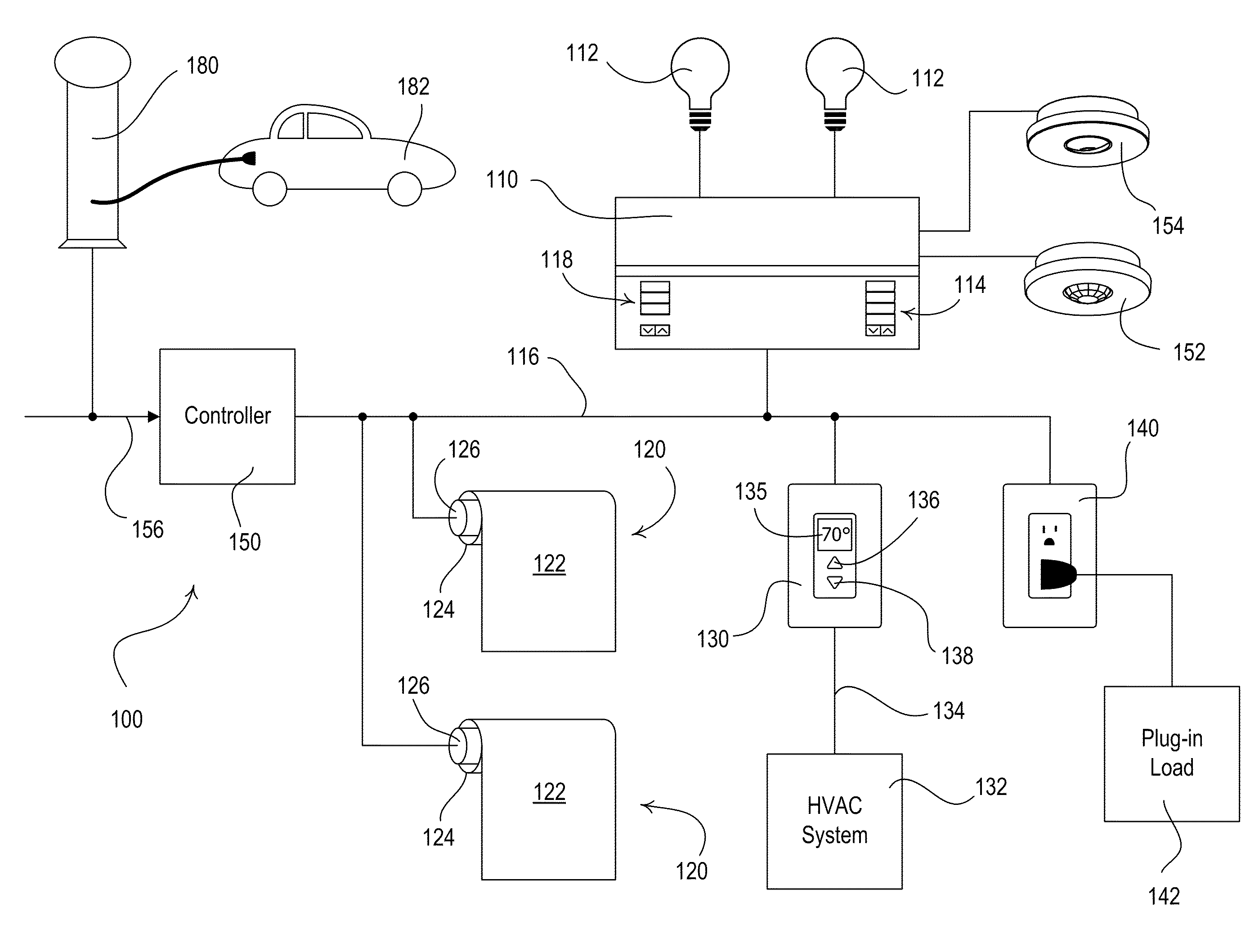
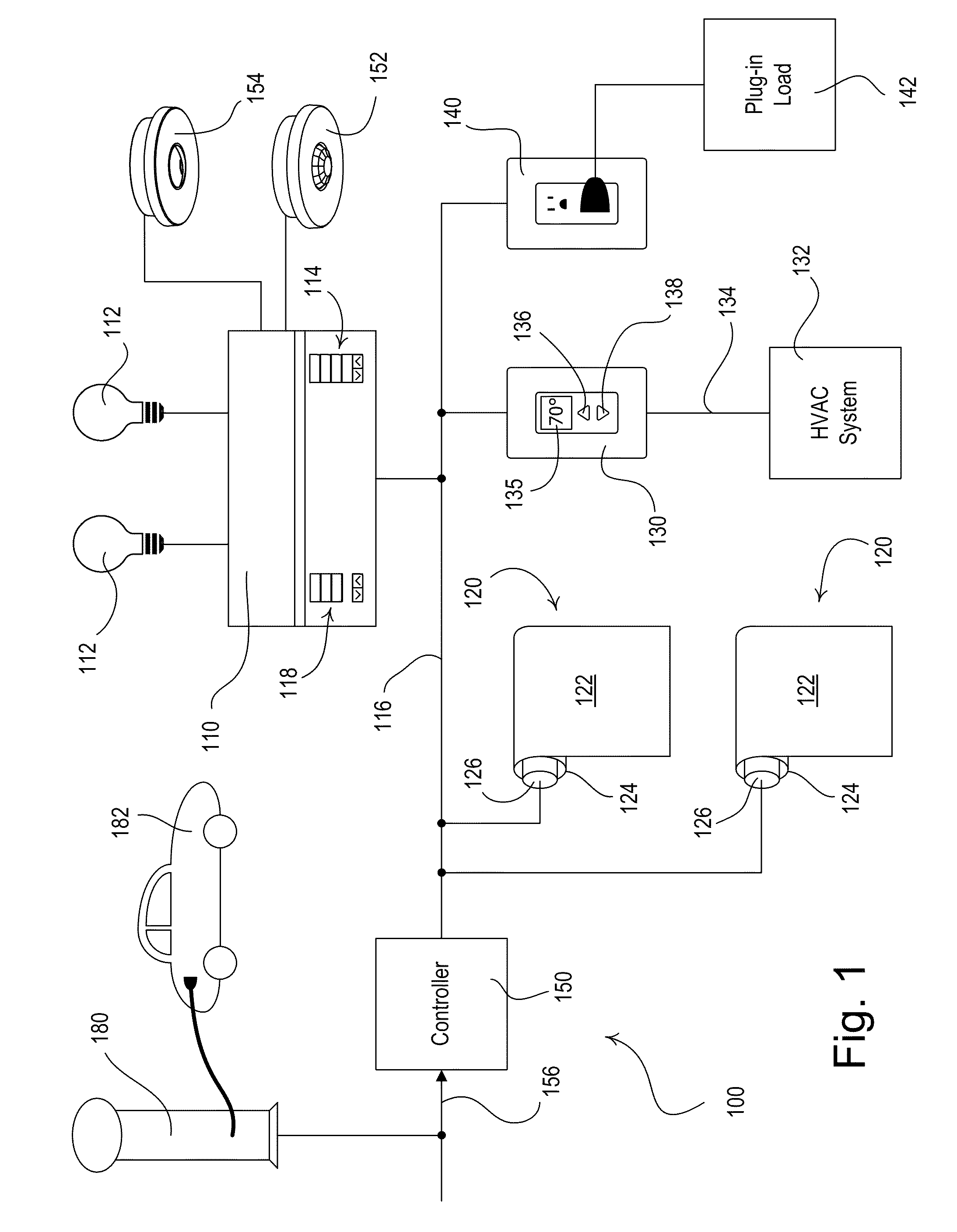
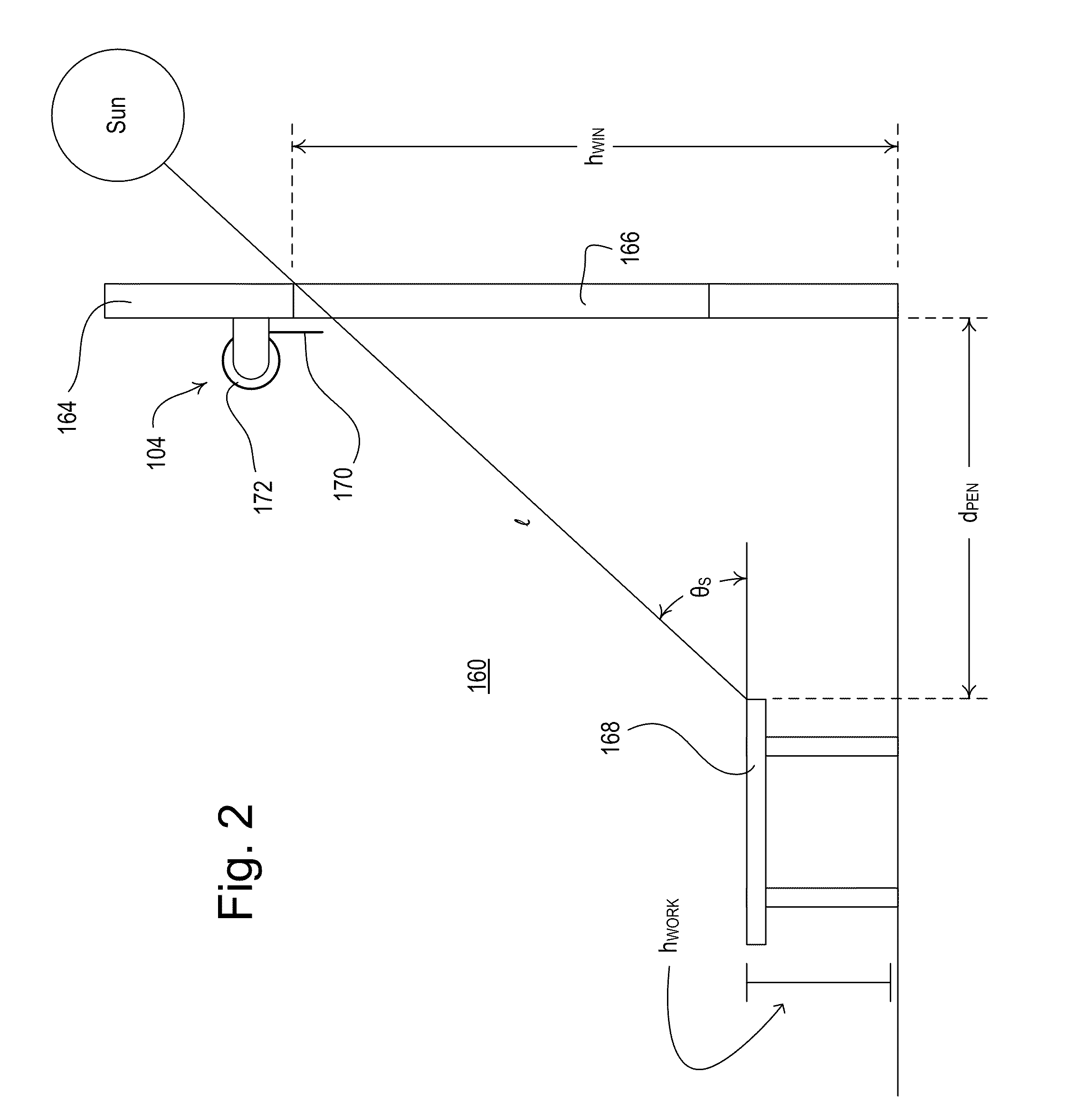
[0055]FIG. 1 is a simplified block diagram of a centralized load control system 100 that may be installed in a building (such as a commercial building) according to the present invention. The load control system 100 comprises a multi-zone lighting control device 110 that is operable to control the amount of power delivered from an alternating-current (AC) power source (not shown) to one or more lighting loads 112 for adjusting the intensities of the lighting loads. The lighting load 112 may be located in a space 160 (FIG. 2) of the building to thus control the amount of electric light (i.e., artificial light) in the space. The lighting loads 112 may comprise, for example, incandescent lamps, halogen lamps, gas discharge lamps, fluorescent lamps, compact fluorescent lamps, high-intensity discharge (HID) lamps, magnetic low-voltage (MLV) lighting loads, electronic low-voltage (ELV) lighting loads, light-emitting diode (LED) light sources, hybrid light sources comprising two or more di...

fourth embodiment

[0075]Alternatively, the load control system 100 could comprise a visual display, such as a liquid-crystal display (LCD) screen, for providing a visual indication that the load control system 100 is operating in the energy-savings mode and for providing information regarding the total power consumption of the load control system and the amount of energy savings, as well as an indication of when the electric vehicle charger 180 is charging the electric vehicle 182. An example of a visual display for providing energy savings information is described in greater detail in commonly-assigned U.S. patent application Ser. No. 12 / 044,672, filed Mar. 7, 2008, SYSTEM AND METHOD FOR GRAPHICALLY DISPLAYING ENERGY CONSUMPTION AND SAVINGS, the entire disclosure of which is hereby incorporated by reference. In addition, the load control system 100 could comprise a dynamic keypad for receiving user inputs (e.g., dynamic keypad 1700 of the fourth embodiment as shown in FIG. 24 and described in greate...

second embodiment

[0122]FIG. 16 is a simplified flowchart of a planned demand response procedure 1200 executed by the controller 150 of the load control system 100 according to the present invention. In response to receiving a planned demand response command, the controller 150 controls the load control system 100 to reduce the total power consumption at a predetermined start time tSTART in the future, for example, at noon on the day after the planned demand response command was received. The controller 150 is operable to “pre-condition” (i.e., pre-cool or pre-heat) the building before the start time tSTART of the planned demand response command, such that the HVAC system 132 will be able to consume less power during the planned demand response event (i.e., after the start time). To pre-condition the building before a planned demand response event, the controller 150 is operable to pre-cool the building when the HVAC system 132 is in the cooling mode and will be cooling the building during the presen...


PUM


Abstract

A load control system for a building having a lighting load, a window, a heating and cooling system, and an electric vehicle charger for charging a vehicle (e.g., an electric or hybrid vehicle) operates in an energy-savings mode to reduce the total power consumption of the load control system when the vehicle charger is presently charging the vehicle. The load control system may comprise a lighting control device for controlling the intensity of the lighting load, a daylight control device for adjusting the amount of natural light admitted through the window, and a temperature control device for controlling a setpoint temperature of the heating and cooling system to thus control a present temperature in the building. When the vehicle charger is presently charging the vehicle, the load control system automatically controls the lighting control device, the daylight control device, and the temperature control device to decrease the total power consumption of the load control system.

Description

CROSS REFERENCE TO RELATED APPLICATIONS[0001]This is a continuation-in-part application of commonly-assigned, co-pending U.S. patent application Ser. No. 12 / 845,016, filed Jul. 28, 2010, entitled LOAD CONTROL SYSTEM HAVING AN ENERGY SAVINGS MODE, which claims priority from U.S. Provisional Patent Application No. 61 / 230,001, filed Jul. 30, 2009, and U.S. Provisional Application No. 61 / 239,988, filed Sep. 4, 2009, both entitled LOAD CONTROL SYSTEM HAVING AN ENERGY SAVINGS MODE, the entire disclosures of which are hereby incorporated by reference.BACKGROUND OF THE INVENTION[0002]1. Field of the Invention[0003]The present invention relates to a load control system for a plurality of electrical loads in a building, and more particularly, to a load control system for controlling the lighting intensities of lighting loads, the positions of motorized window treatments, and the temperature of the building in order to reduce the total power consumption of the load control system.[0004]2. Desc...

Claims


Application Information

Patent Timeline
IPC IPC(8): H02J3/14
CPCE06B9/24E06B9/68F24F5/0046F24F2011/0075G05B15/02H04L12/10Y02B20/46H04L12/28H05B37/0218H05B37/0227Y02B10/20Y02B10/24Y02B20/40H04L12/14F24F11/46Y02A30/272H05B47/11H05B47/175H05B47/115
Inventor PESSINA, MICHAEL W.
Owner LUTRON TECH CO LLC
Why Eureka
Try Eureka