Half-power buffer amplifier

Active Publication Date: 2011-10-27
HIMAX TECH LTD
View PDF1 Cites 2 Cited by
  • Summary
  • Abstract
  • Description
  • Claims
  • Application Information

AI Technical Summary

Benefits of technology

[0011]In view of the foregoing, it is an object of the embodiment of the present invention to provide a half-p

Problems solved by technology

As a result, the LCD, particularly the large-size and/or high-resolution LCD, consumes immense power.
On the other hand, as the power is precious to a portable electronic device with the LCD, the power consumption of

Method used


Image

  • Half-power buffer amplifier
  • Half-power buffer amplifier
  • Half-power buffer amplifier

Examples


Example

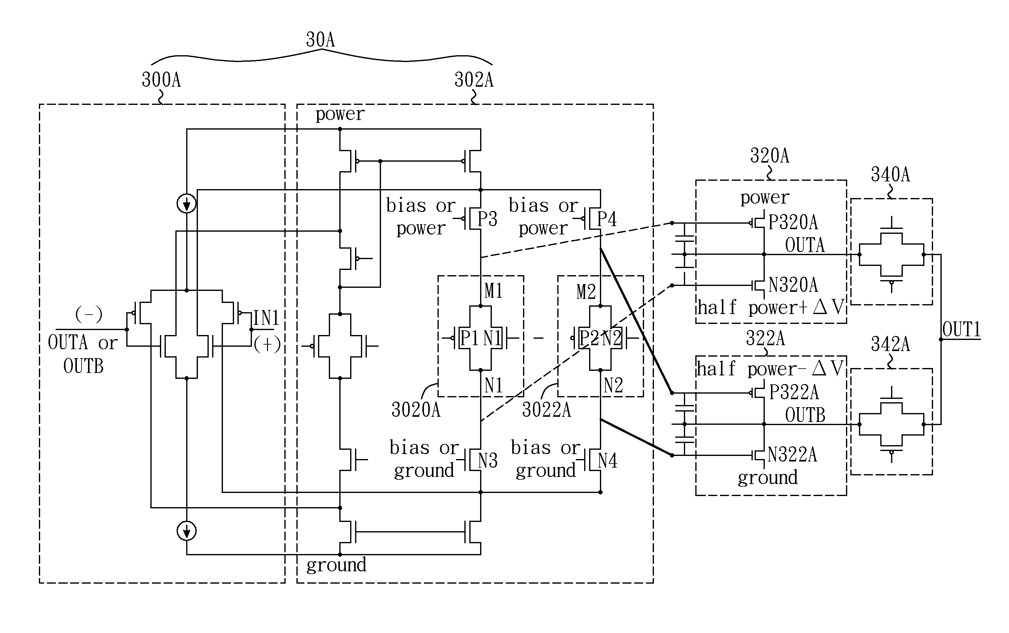
[0021]FIG. 3 shows a half-power buffer amplifier according to one embodiment of the present invention. Although the embodiment illustrated here is adapted to a source driver of a liquid crystal display (LCD) (now shown), it is, however, appreciated by those skilled in the pertinent art that this embodiment (and other embodiments) may be well adapted to other display panels.

[0022]In the embodiment, at least one half-power buffer amplifier (abbreviated as buffer amplifier hereinafter) is used in the source driver of the LCD. In the example, two buffer amplifiers, that is, a first buffer amplifier 3A and a second buffer amplifier 3B, are illustrated in the figure for two channels CH1 and CH2 respectively. As shown in FIG. 4, the output OUT1 of the first buffer amplifier 3A is utilized as an output stage of the source driver to drive the first row of the LCD, and the output OUT2 of the second buffer amplifier 3B is utilized as another output stage of the source driver to drive the secon...


PUM


Abstract

A half-power buffer amplifier is disclosed. A buffer stage includes a first-half buffer stage and a second-half buffer stage, wherein an output of the first-half buffer stage is controllably fed back to a rail-to-rail differential amplifier, and an output of the second-half buffer stage is controllably fed back to the rail-to-rail differential amplifier. The switch network controls the connection between the outputs of the buffer stage and an output node of the half-power buffer amplifier in a manner such that a same pixel, with respect to different frames, of a display panel is driven by the same rail-to-rail differential amplifier. In one embodiment, the rail-to-rail differential amplifier and the buffer stage comprise half-power transistors operated within and powered by half of a full range spanning from power to ground.

Description

CROSS-REFERENCE TO RELATED APPLICATIONS[0001]The present invention is a continuation-in-part of U.S. application Ser. No. 12 / 628,212, filed on Nov. 30, 2009 and entitled HALF-POWER BUFFER AMPLIFIER, the complete subject matter of which is hereby incorporated herein by reference.BACKGROUND OF THE INVENTION[0002]1. Field of the Invention[0003]The present invention generally relates to a buffer amplifier, and more particularly to a half-power buffer amplifier adaptable to a liquid crystal display (LCD).[0004]2. Description of Related Art[0005]A liquid crystal display (LCD) typically includes rows and columns of picture elements (or pixels) arranged in matrix form. Each pixel includes a thin film transistor (TFT) and a pixel electrode formed on a substrate (or panel). The gates of the TFTs in the same row are connected together through a gate line, and controlled by a gate driver (or scan driver). The sources of the TFTs in the same column are connected together through a source line, a...

Claims


Application Information

Patent Timeline
IPC IPC(8): H03B1/00
CPCH03F3/45192H03F2203/45726H03F3/45475H03F3/45219
Inventor HUANG, HUNG-YUWANG, CHEN-YU
Owner HIMAX TECH LTD
Why Eureka
Try Eureka