Driving circuit for source driving chips and liquid crystal display panel

Active Publication Date: 2017-06-08
TCL CHINA STAR OPTOELECTRONICS TECH CO LTD
View PDF1 Cites 2 Cited by
  • Summary
  • Abstract
  • Description
  • Claims
  • Application Information

AI Technical Summary

Benefits of technology

[0007]An embodiment of the present disclosure provides a driving circuit for a source dr

Problems solved by technology

In terms of the LCD panel, larger screens have higher resolution, and thus the power consumption is naturally larger However, the greater power consumption results in higher temperature of the liquid crystal panel, and thus the operation stability of the liquid crystal panel is affected

Method used


Image

  • Driving circuit for source driving chips and liquid crystal display panel
  • Driving circuit for source driving chips and liquid crystal display panel
  • Driving circuit for source driving chips and liquid crystal display panel

Examples


Example

[0042]The following description with reference to the accompanying drawings is provided to explain the exemplary embodiments of the disclosure. It will be apparent, however, that the disclosure may be practiced by one or more embodiments, and the specific embodiments provided herein cannot be interpreted to limit the disclosure. On the contrary, those embodiments are provided to explain the principle and the application of the disclosure such that those skilled in the art may understand the various embodiments of the disclosure and the various modifications for specific expected application.

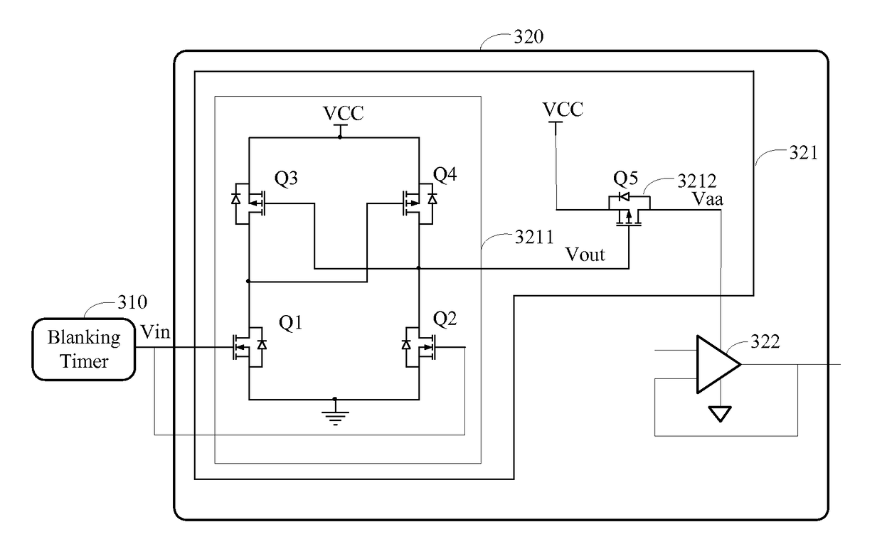
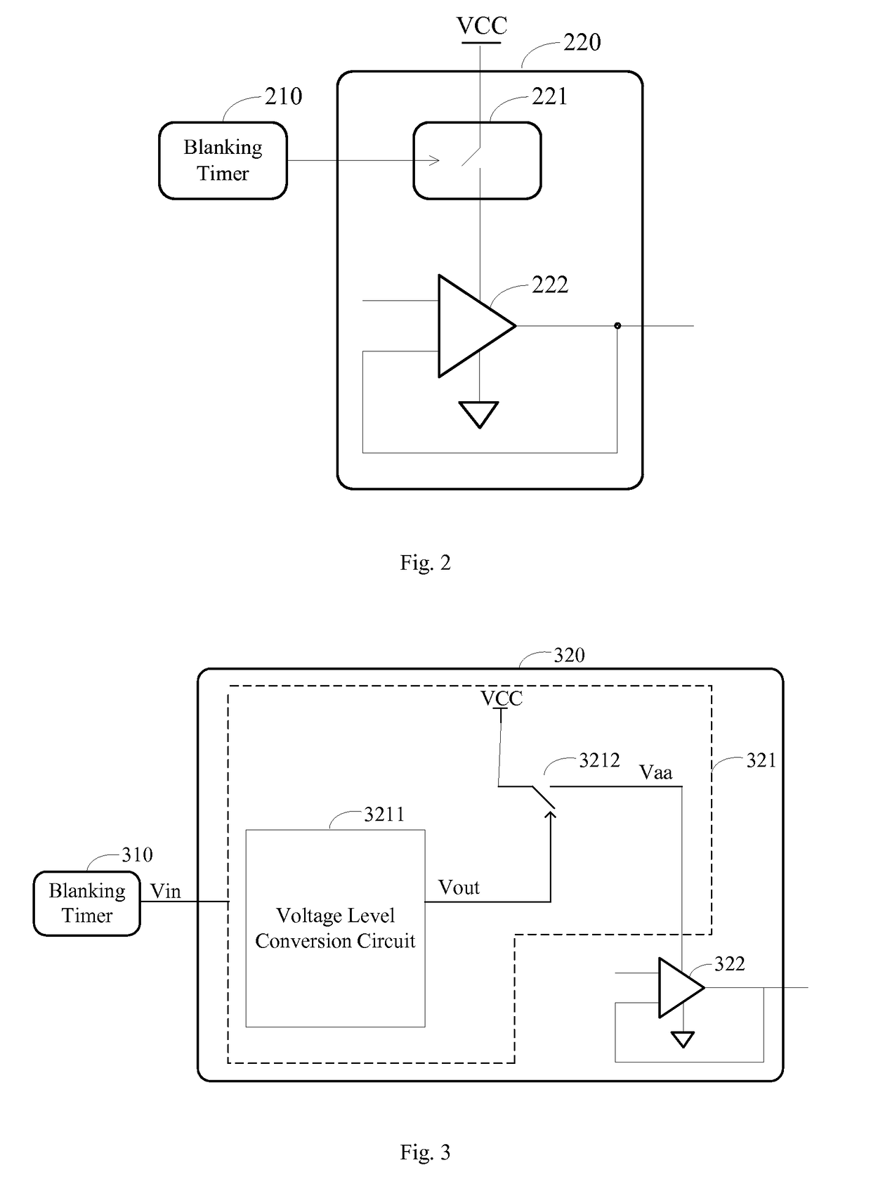
[0043]Please refer to FIG. 2. FIG. 2 is a circuit diagram of the driving circuit for a source driving chip according to an embodiment of the present disclosure. The driving circuit for a source driving chip of the present embodiment comprises: a blanking timer 210, a switching unit 221 and a buffer amplifier 222. In one embodiment, the switching unit 221 and the buffer amplifier 222 are integrate...


PUM


Abstract

The present disclosure discloses a driving circuit for a source driving chip. In the driving circuit for a source driving chip, an output terminal of the blanking timer is connected to a control terminal of the switching unit; an input terminal of the switching unit is connected to a power supply source; an output terminal of the switching unit is connected to a supply terminal of the buffer amplifier. The blanking timer is used to generate a control signal; wherein, the control signal is a first voltage level during a row blanking interval or a frame blanking interval; the control signal is a second voltage level during the row non-blanking interval or the frame non-blanking interval. The driving circuit for a source driving chip of the present disclosure can effectively reduce the power consumption.

Description

[0001]This application claims the benefit of, and priority to, China Patent Application No. 201510470829.2, filed Aug. 4, 2015, titled “Driving Circuit For Source Driving Chips And Liquid Crystal Display”, the entire contents of which are incorporated by reference herein in its entirety.BACKGROUND[0002]Technical Field[0003]The disclosure is related to a liquid crystal display field, and more particular to a driving circuit for a source driving chip and a liquid crystal display panel.[0004]Related Art[0005]As technology advances, users increasingly demand higher visual experience. A variety of electronic products with high-definition and large-screen become increasingly popular. In terms of the LCD panel, larger screens have higher resolution, and thus the power consumption is naturally larger However, the greater power consumption results in higher temperature of the liquid crystal panel, and thus the operation stability of the liquid crystal panel is affected. Moreover, it does not...

Claims


Application Information

Patent Timeline
IPC IPC(8): G09G3/36G02F1/1345G02F1/1368
CPCG09G3/3648G02F1/1368G02F1/13454G09G2300/0408G09G2310/061G09G2310/08G09G2330/023G09G2310/0291G09G3/3688G09G2330/021
Inventor WU, JINGJINGXIONG, ZHI
Owner TCL CHINA STAR OPTOELECTRONICS TECH CO LTD
Why Eureka
Try Eureka