Head substrate, printhead, and head cartridge

Inactive Publication Date: 2009-03-05
CANON KK
View PDF9 Cites 4 Cited by
  • Summary
  • Abstract
  • Description
  • Claims
  • Application Information

AI Technical Summary

Benefits of technology

[0035]The invention is particularly advantageous since a current flowing through series-connected PMOS and NMOS transistors which constitute a level converter can be controlled to be small, decreasing the power consumption of the level converter. Heat generated by the head substrate having the level converter can be suppressed to suppr

Problems solved by technology

However, there is a limit on integrating high-voltage tolerant element structures by the miniaturization process, and it is difficult to arrange them at high density.
As a result, the level converter consumes an enormous amount of current.
In a recent printhead in which many nozzles and switching

Method used


Image

  • Head substrate, printhead, and head cartridge
  • Head substrate, printhead, and head cartridge
  • Head substrate, printhead, and head cartridge

Examples


Example

First Embodiment

[0084]FIG. 5 is a circuit diagram showing an equivalent circuit which is integrated on a head substrate and includes a level converter, heater, and driver transistor according to the first embodiment. In FIG. 5, the same reference numerals as those described in the prior art denote the same parts, and a description thereof will not be repeated.

[0085]On this head substrate, similar to the prior art, a signal for driving a heater is processed by an AND gate 206 serving as a heater selector which forms part of a logic circuit. Then, the processed signal is output with the amplitude of a logic voltage (VDD voltage). A level converter 205 boosts the output voltage to have the amplitude of the second power supply voltage VHT higher than the VDD voltage. The boosted voltage drives the gate of a driver transistor 204.

[0086]As is apparent from a comparison between FIGS. 5 and 13, the head substrate according to the first embodiment comprises a bias circuit 401 for controlling...

Example

Second Embodiment

[0112]FIG. 10 is a circuit diagram showing an equivalent circuit which is integrated on a head substrate and includes a level converter, heater, and driver transistor according to the second embodiment. In FIG. 10, the same reference numerals as those described in the prior art denote the same parts, and a description thereof will not be repeated.

[0113]On this head substrate, similar to the prior art, a signal for driving the heater is processed by an AND gate or logic circuit 206, and output with the amplitude of a logic power supply voltage (VDD voltage). The output voltage is applied to two input terminals IN1 and IN2 of a level converter 205.

[0114]As is apparent from a comparison between FIGS. 5 and 10, the level converter 205 of the head substrate according to the second embodiment receives a plurality of logic signals. The level converter 205 simultaneously performs logical operation and signal amplitude conversion for these input logic signals. A bias circuit...

Example

Third Embodiment

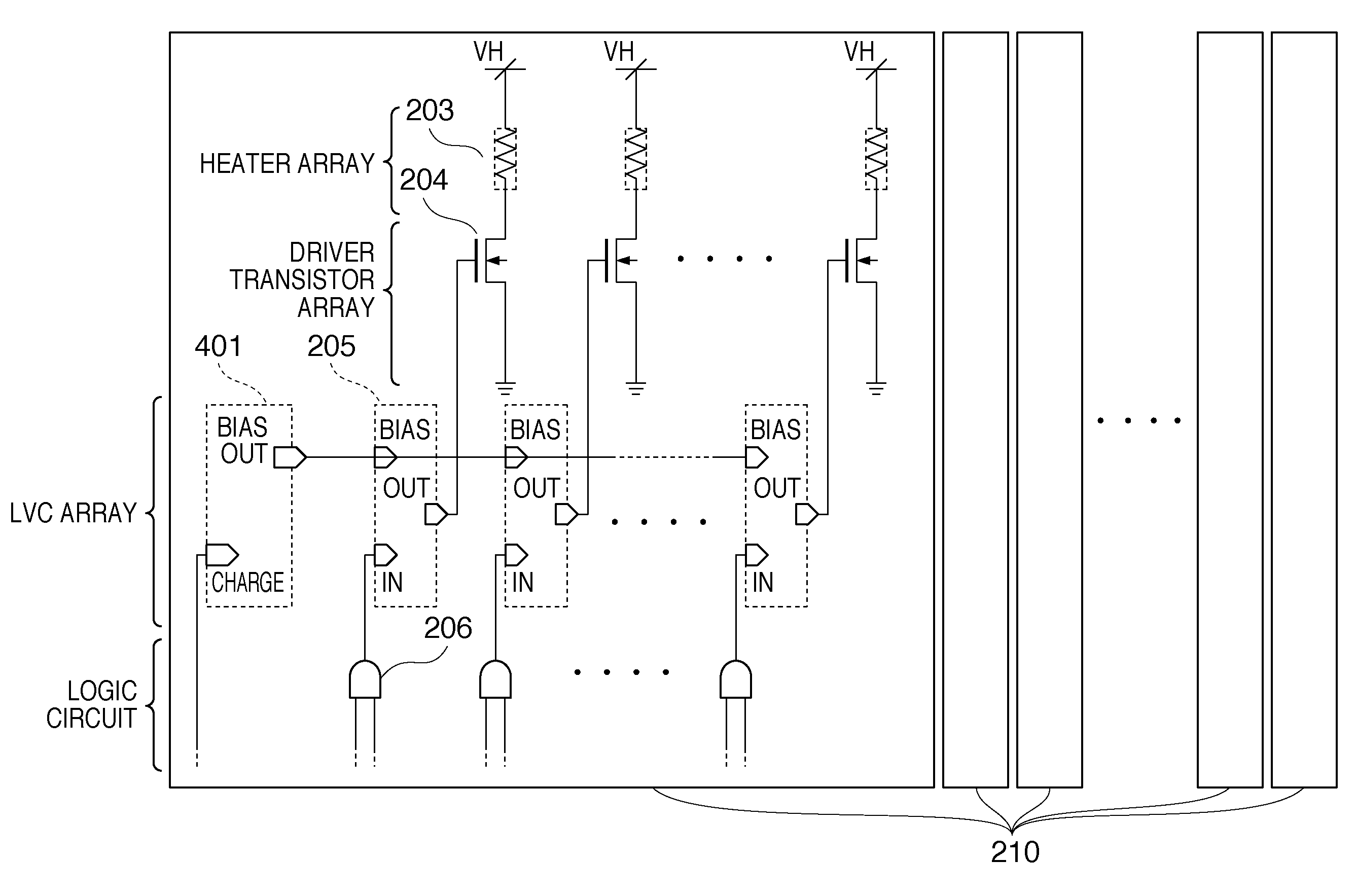
[0121]FIG. 12 is a circuit diagram showing an equivalent circuit which is integrated on a head substrate and includes a level converter, heater, and driver transistor according to the third embodiment. The third embodiment shows a circuit which time-divisionally drives heaters in accordance with the block. In FIG. 12, the same reference numerals as those described in the prior art and first embodiment denote the same parts, and a description thereof will not be repeated. A bias circuit 401 is identical to that described in the first embodiment with reference to FIG. 7, and a level converter 205 is identical to that described in the first embodiment with reference to FIG. 6.

[0122]FIG. 12 shows a plurality of circuit blocks 210. Each circuit block 210 has a 1-bit shift register (S / R) 1305 which serially receives a data signal DATA from a logic circuit (not shown). In synchronism with a clock signal (not shown), the shift register (S / R) 1305 receives the data signal DAT...


PUM


Abstract

The following arrangement is added to a head substrate including a plurality of electrothermal transducers, a plurality of switching elements which drive the plurality of electrothermal transducers, and a logic circuit which drives the plurality of switching elements. That is, the head substrate includes a plurality of level converters which correspond to the respective switching elements, and apply a voltage obtained by boosting a logic voltage. Further, the head substrate includes a bias circuit which applies a bias voltage lower than the boosted voltage to the plurality of level converters.

Description

BACKGROUND OF THE INVENTION[0001]1. Field of the Invention[0002]The present invention relates to a head substrate, printhead, and head cartridge. Particularly, the present invention relates to a head substrate obtained by forming, on a single substrate, electrothermal transducers for generating heat energy necessary to print, and switching elements for driving the electrothermal transducers, a printhead using the head substrate, and a head cartridge using the printhead.[0003]2. Description of the Related Art[0004]Conventionally, the electrothermal transducer (heater) of an inkjet printhead and a switching element for switching a heater to be driven are formed on a single substrate using a semiconductor process technique, as disclosed in the U.S. Pat. No. 6,290,334. Many proposals have been made for a layout arrangement in which heaters and switching elements are integrated on a head substrate. When an NMOS transistor is employed as a switching element, a level converter (LVC) is int...

Claims


Application Information

Patent Timeline
IPC IPC(8): H03L5/00B41J2/015
CPCB41J2/04541B41J2/04548B41J2/0455B41J2/0458B41J2/0457
Inventor SAKURAI, MASATAKAKASAI, RYO
Owner CANON KK
Why Eureka
Try Eureka