Engine system having improved efficiency

a technology of engine system and efficiency, applied in the direction of electric motor starter, electric energy management, electric devices, etc., can solve the problems of excessive temperature conditions, potential thermal damage, and substantial inefficiencies that may remain, and achieve the effect of reducing high temperature conditions and efficient temperature rang

Inactive Publication Date: 2008-09-23
FORD GLOBAL TECH LLC
View PDF14 Cites 89 Cited by
  • Summary
  • Abstract
  • Description
  • Claims
  • Application Information

AI Technical Summary

Benefits of technology

[0004]Various approaches have attempted to provide an acceptable yet efficient operating environment for the thermoelectric device, including the use of variable heat exchangers arranged between the heat source and the device. However, the additional hardware can increase the cost of the vehicle, reduce efficiency via increased weight or pumping losses or create additional issues, under some conditions.
[0007]In this way, the temperature of the engine, exhaust passage, and / or catalyst may be controlled, for example, by providing heating during lower temperature conditions, while electrical energy generation may be achieved during higher temperature conditions.
[0009]In this way, synergy between the free-piston engine in a full series or other HEV configuration and the thermoelectric conversion system may be achieved by varying operation of the free-piston engine in response to the temperature at the thermoelectric devices. The thermoelectric devices may then be placed closer to the heat source, such as directly at or surrounding the engine where the temperature may be controlled within a more efficient temperature range while reducing high temperature conditions that may otherwise occur. Note that variable heat exchangers arranged between the heat source and the device may additionally be used, along with fixed piston engines, if desired.

Problems solved by technology

While some efficiency gains may be achieved by supplementing the operation of the engine with that of a motor, substantial inefficiencies may nevertheless remain.
However, one issue with the thermoelectric device includes the potential for thermal damage caused by excessive temperatures.
Thus, while large temperature gradients may be useful to efficiently recapture rejected thermal energy, if temperatures are too high, protection of the device from excessive temperature conditions may occur.
However, the additional hardware can increase the cost of the vehicle, reduce efficiency via increased weight or pumping losses or create additional issues, under some conditions.

Method used


Image

  • Engine system having improved efficiency
  • Engine system having improved efficiency
  • Engine system having improved efficiency

Examples


Embodiment Construction

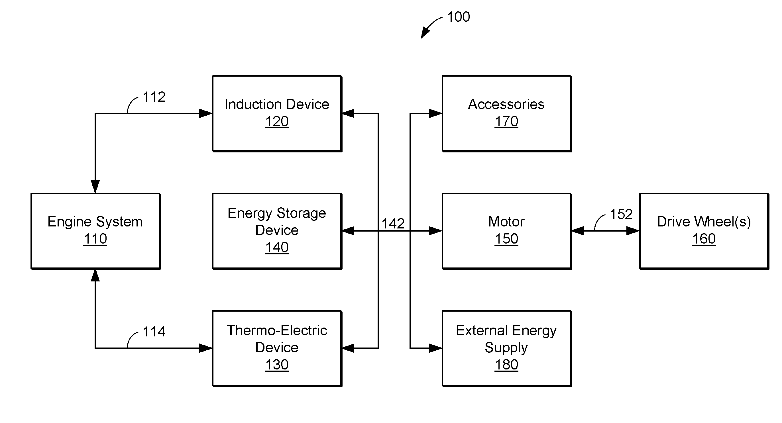
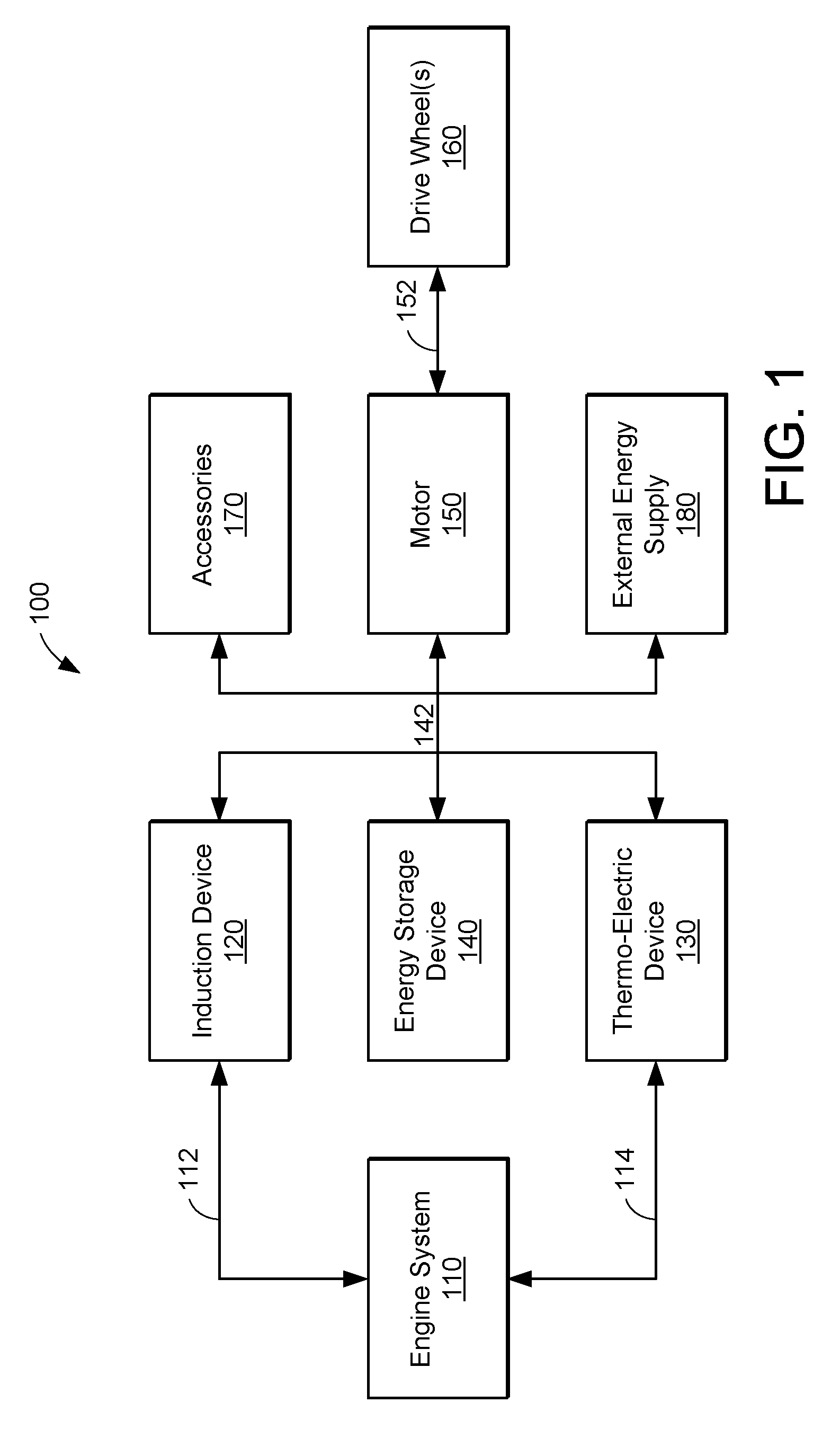
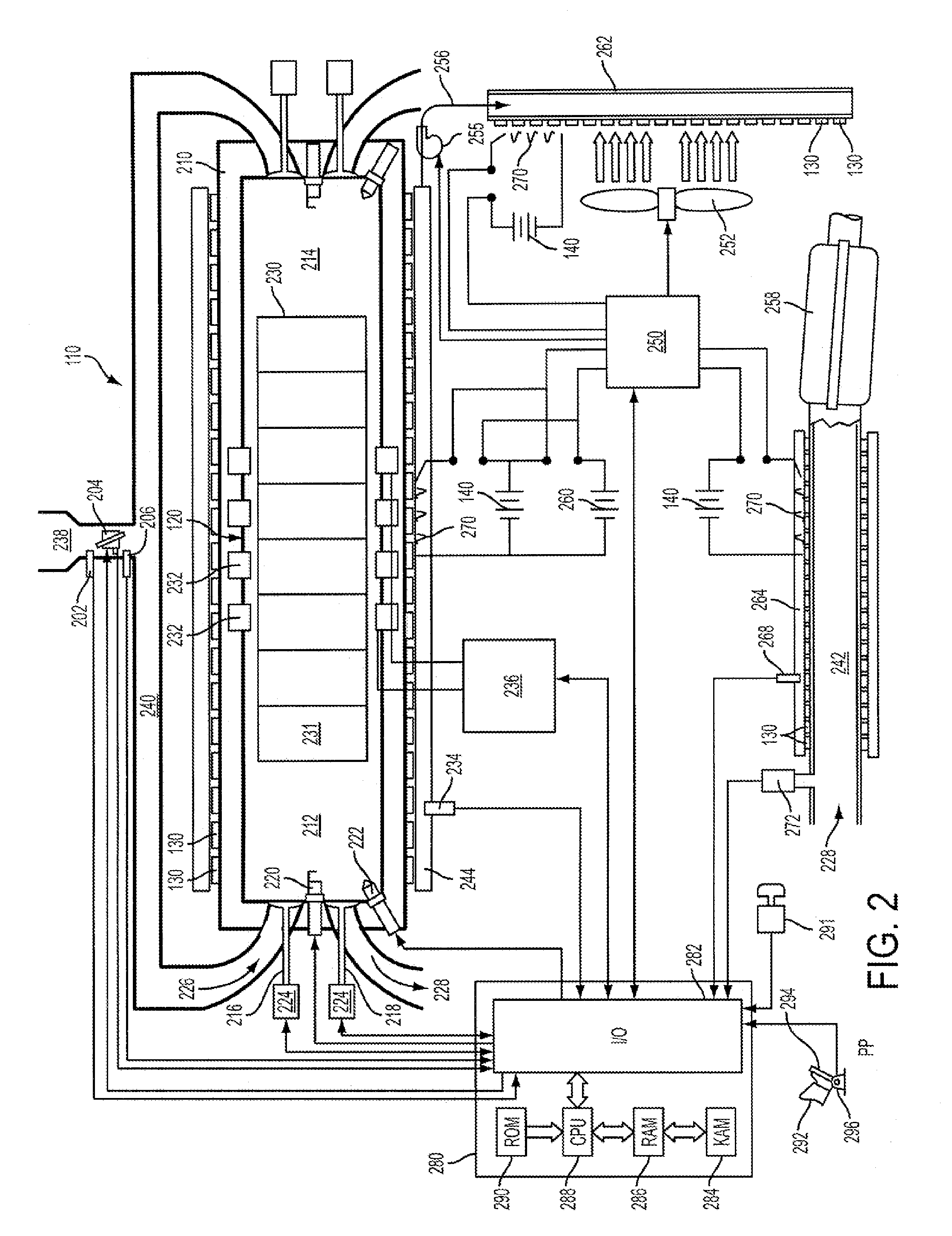
[0014]The present disclosure relates generally to a hybrid propulsion system for a vehicle such as an automobile. The hybrid propulsion system described herein may utilize the synergy between a fuel combusting engine, a drive motor, and one or more thermoelectric devices to achieve increased efficiency, lower products of combustion, and / or improved drivability, under some conditions.

[0015]In at least one embodiment, a full series hybrid vehicle configuration may be used that enables the engine to be operated independent of the requested wheel torque. For example, by providing the desired propulsive force via a motor, the engine may be operated in response to other operating parameters. As one example, operation of the engine may be varied in response to the temperature of the thermoelectric conversion system to reduce or prevent unsuitably high temperature conditions that may cause damage or decrease the lifecycle of the thermoelectric device.

[0016]Still other synergies may be reali...


PUM


Abstract

A propulsion system for a vehicle, comprising of an internal combustion engine, a thermoelectric device in thermal communication with the engine, and a control system for controlling the engine and the thermoelectric device during a first mode, supply electrical energy to the thermoelectric device to cause the thermoelectric device to produce at least some heat, and during a second mode, operate the engine to produce at least some heat, where the thermoelectric device is operated to convert a temperature gradient at the thermoelectric device to electrical energy.

Description

BACKGROUND AND SUMMARY[0001]Some automobiles utilize an internal combustion engine to provide at least a portion of the wheel power requested by the driver. As one example, a hybrid electric vehicle (HEV) can control the engine to operate under select conditions, while an electric motor can separately provide the requested propulsive effort. While some efficiency gains may be achieved by supplementing the operation of the engine with that of a motor, substantial inefficiencies may nevertheless remain. As one prophetic example, up to 75% of the fuel energy consumed by an internal combustion engine may be lost to unexploited thermal energy, under some conditions. Of this, approximately 35% may be lost to the exhaust gases of the engine, 20% to the coolant or cooling process, and another 20% to thermal radiation.[0002]Some vehicle propulsion systems have attempted to address the above issues by reducing the amount of time that the engine is operating or by downsizing the engine by incr...

Claims


Application Information

Patent Timeline
Patent Type & Authority Patents(United States)
IPC IPC(8): F02B71/04B60K1/00F02N17/02H01L35/28F02N19/02
CPCB60K6/24B60W10/06B60W10/08B60W20/00F02D41/021F02N19/02B60L1/003B60L1/02B60L3/0023B60L7/12B60L11/14B60L11/1861B60L11/1864B60L15/2009F01N5/025B60K6/28Y10S903/903F02D41/0087F02D41/3076F02D2200/503F02N11/0814F02N11/0818Y02T10/6286Y02T10/6295Y02T10/16Y02T10/166B60L2240/12B60L2240/36B60L2240/421B60L2240/423B60L2240/441B60L2240/443B60L2240/445B60L2270/12Y02T90/16Y02T10/70Y02T10/72B60L50/16B60L58/12B60L58/21Y02T10/12Y02T10/40Y02T10/62Y02T10/64Y02T10/7072H10N10/10F02G5/00F25B21/00B60K6/20B60K13/04B60W2510/068
Inventor ELWART, SHANE
Owner FORD GLOBAL TECH LLC
Why Eureka
Try Eureka