Systems and methods for cooling data centers and other electronic equipment

Inactive Publication Date: 2011-08-11
IT AIRE +2
View PDF9 Cites 86 Cited by
  • Summary
  • Abstract
  • Description
  • Claims
  • Application Information

AI Technical Summary

Benefits of technology

[0007]The present disclosure is directed to systems and methods for controlling the environment within data centers and other enclosed spaces and to data centers and other enclosed spaces utilizing such systems and methods. These systems and methods may include independent control of a flow rate of air provided to the enclosed space by an environmental control assembly and a temperature of air provided to the enclosed space by the environmental control assembly. These systems and methods also may include controlling the relative humidity of the air within the enclosed space and/or controlling a differential pressure between the enclosed space and an ambient environment proximal to the enclosed space. The systems and methods disclosed herein may include the use of a novel fluid drive assembly.
[0008]In some embodiments, the flow rate of air provided to the enclosed space may be controlled based at least in part on a pressure measurement. In some embodiments, the pressure measurement may include one or more differential pressure measurements. In some embodiments, the one or more differential pressure measurements may include a pressure differential between a hot region, or aisle, and a cold region, or aisle, within the enclosed space. In some embodiments, the one or more differential pressure measurements may include a pressure differential between an intake region and an exhaust region within the enclosed space. In some embodiments, controlling the flow rate of air provided to th

Problems solved by technology

Efficient heat removal may decrease operational costs, increase equipment lifetime, and decrease equipment downtime.
Thus, cooling power requirements may have a significant impact on the overall energy consumption of the facility.
As additional pieces of electronic equipment are installed, such as during the build-out of a data center, the overall heat load may change significantly.
In order to maintain effective cooling, the initial installation of cooling equipment may be significantly oversized, requiring it to run at reduced efficiency until the build-out nears completion, which may take months or even years.
Alternatively, the cooling equipment may be installed in stages, thereby increasing incremental operating efficiency but requiring frequent and inconvenient construction.
Similarly, since the ambient environment in the vicinity of the ele

Method used


Image

  • Systems and methods for cooling data centers and other electronic equipment
  • Systems and methods for cooling data centers and other electronic equipment
  • Systems and methods for cooling data centers and other electronic equipment

Examples


Embodiment Construction

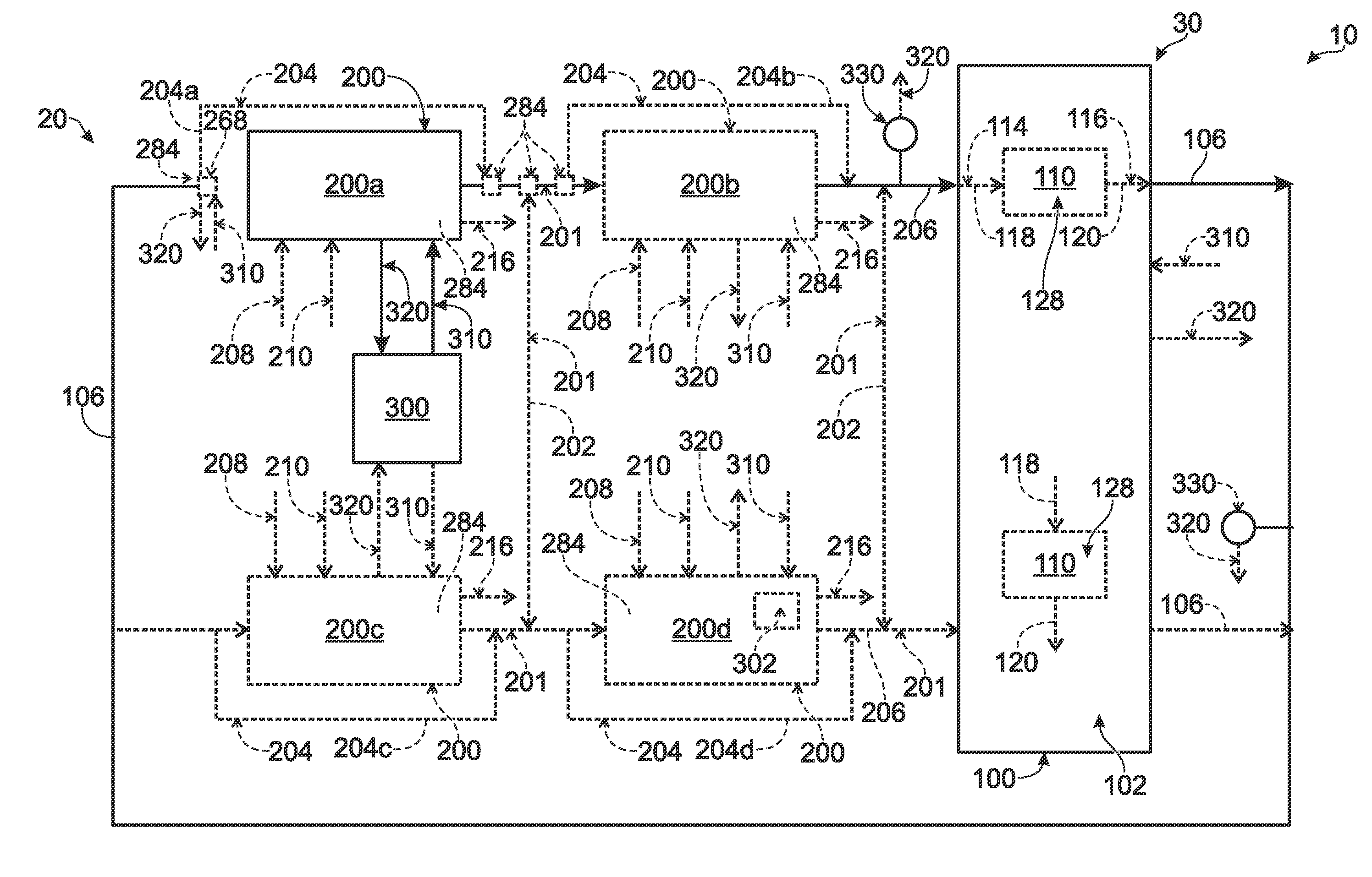
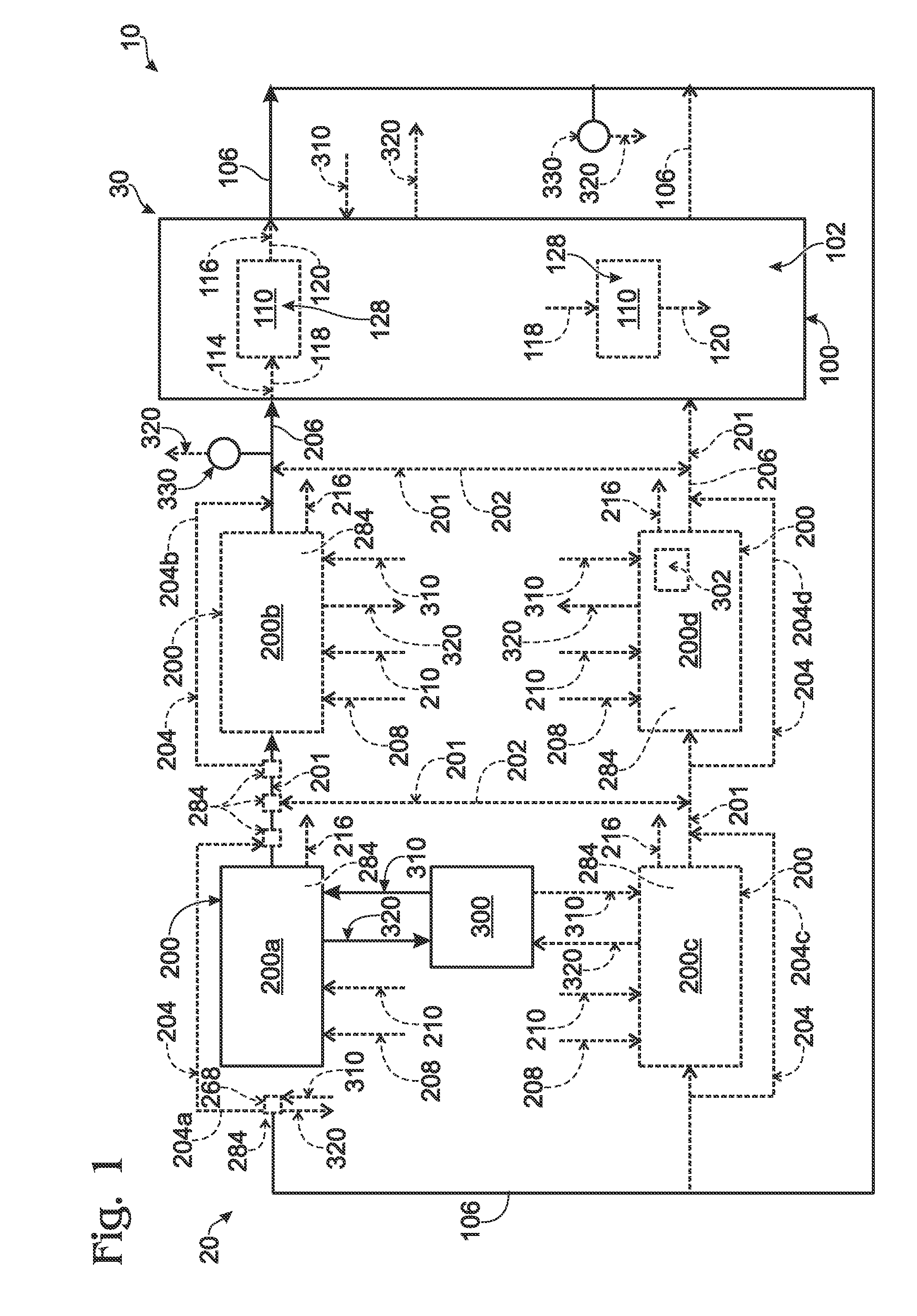
[0027]Illustrative, non-exclusive examples of an environmental control system 10 according to the present disclosure are shown schematically in FIG. 1. Environmental control system 10 includes an environmental control assembly 20 and a space 30 to be controlled. As discussed in more detail herein, space 30 may be, or include, an enclosed space 100, which may be a data center or other space designed to house operating electrical (such as computing and / or communications) equipment. Environmental control assembly 20 receives a return air stream 106 from space 30, processes return air stream 106 as a process air stream 201 internal to the environmental control assembly, generates supply, or discharge, air stream 206, and supplies discharge air stream 206 back to space 30. In a general sense, environmental control assembly 20 may control the temperature, pressure, relative humidity, and / or other variables impacting the local environment within space 30 by processing return air stream 106...


PUM


Abstract

Temperature, humidity, and pressure control systems and methods for enclosed spaces, including data centers. In some embodiments, the rotational frequency of the air supply fans is controlled based on a pressure associated with the enclosed space. In some embodiments, the rotational frequency of the air supply fans is controlled based on a pressure differential between an inlet region and an exhaust region within the enclosed space. In some embodiments, air within the inlet region is segregated from air within the exhaust region. In some embodiments, the cooling capacity of the cooling equipment is controlled responsive to a temperature associated with the enclosed space. In some embodiments, the cooling capacity is controlled based on a temperature associated with the inlet region of the enclosed space. In some embodiments, the humidity within the enclosed space is controlled.

Description

RELATED APPLICATION[0001]The present application claims priority to similarly entitled U.S. Provisional Patent Application Ser. No. 61 / 302,645, which was filed on Feb. 9, 2010, and the complete disclosure of which is hereby incorporated by reference.FIELD OF THE DISCLOSURE[0002]The present disclosure is directed generally to systems and methods to control the environment within enclosed spaces, and more specifically to systems and methods for controlling environmental variables such as temperature, pressure, and / or relative humidity in data centers and other enclosed spaces containing electronic equipment.BACKGROUND OF THE DISCLOSURE[0003]Semiconductor devices are electronic circuits fabricated from a semiconductor material, such as silicon. Historically, the density of these circuits has increased at a dramatic pace, doubling every 18-24 months as described by Moore's Law. This ever-increasing density of semiconductor devices is paralleled by an ever-increasing intensity of heat ge...

Claims


Application Information

Patent Timeline
IPC IPC(8): H05K5/00F24F7/00F24F7/06F24F1/0063
CPCF24F11/008F24F2001/0092Y02B30/545H05K7/20836F24F2011/0042F24F11/30F24F2110/10F24F2110/40F24F11/83G06F1/20F24F13/08F24F13/02F24F1/0007F24F1/0063F24F11/76F24F11/46F24F11/39F24F11/63F24F11/35F24F11/38Y02B30/54F04D13/0686H05K7/20736
Inventor SMITH, KENNETH LANE
Owner IT AIRE
Why Eureka
Try Eureka