
Laboratory central control device based on computer technology

A laboratory and computer technology, applied in water supply devices, circuit devices, drinking water devices, etc., can solve the problems of wasting the time of experimenters, inconvenient for experimenters to use ventilation devices, and poor ventilation effect, and avoid harmful gases. and dust accumulation, reducing water consumption and reducing losses

Inactive Publication Date: 2018-09-28
广东鑫城绿美陶瓷有限公司
View PDF0 Cites 1 Cited by
  • Summary
  • Abstract
  • Description
  • Claims
  • Application Information

AI Technical Summary

Problems solved by technology

[0002] The laboratory is the cradle of science, the base of scientific research, and the source of scientific and technological development. The laboratory plays a very important role in the development of science and technology. The laboratory is an important occasion for high-level academic exchanges and the production place of science and technology. Especially for some chemical laboratories and heat treatment laboratories, some toxic gases or dust particles are easily produced during the experiment. If the laboratory is not ventilated in time, it may affect the health of the experimenters.
[0003] Most of the current laboratory ventilation devices are only connected to an ordinary ventilator through a ventilation pipe to ventilate the laboratory. The electric adjustment of the ventilation rate of the ventilation component is very inconvenient for the experimenters to use the ventilation device, which wastes a lot of time for the experimenters. The threat of harmful gas produced in the environment is very unfavorable to the experimental work of the experimenters

Method used


Image

  • Laboratory central control device based on computer technology
  • Laboratory central control device based on computer technology
  • Laboratory central control device based on computer technology

Examples


Embodiment Construction

[0037] The technical solutions in the embodiments of the present invention will be clearly and completely described below in conjunction with the accompanying drawings in the embodiments of the present invention. Obviously, the described embodiments are only some of the embodiments of the present invention, not all of them. Based on The embodiments of the present invention and all other embodiments obtained by persons of ordinary skill in the art without making creative efforts belong to the protection scope of the present invention.

[0038] In describing the present invention, it should be understood that the terms "upper", "lower", "front", "rear", "left", "right", "top", "bottom", "inner", " The orientation or positional relationship indicated by "outside", etc. is based on the orientation or positional relationship shown in the drawings, which is only for the convenience of describing the present invention and simplifying the description, rather than indicating or implying...


PUM


Abstract

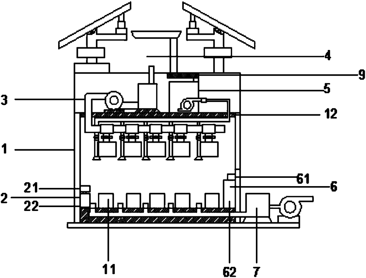
The invention relates to the technical field of computer application and discloses a laboratory central control device based on a computer technology. The laboratory central control device comprises alaboratory, an air pumping assembly, an air delivery assembly, a collecting assembly, a fire extinguishing assembly, a central processing assembly and a constant-temperature and constant-humidity assembly. The components and concentration of gas are sensed by a gas sensor mounted above each experiment table, and data comparison and analysis are carried out through a central processor. Meanwhile,a computer sends an instruction to an air filter to remove harmful gas in the air, and at the same time, a photovoltaic panel carries out electric generation, rain collection and fire extinguishing under the control of the computer, so that the problem of saving water and electricity consumption is solved.

Description

technical field [0001] The invention relates to the field of computer application technology, in particular to a laboratory central control device based on computer technology. Background technique [0002] The laboratory is the cradle of science, the base of scientific research, and the source of scientific and technological development. The laboratory plays a very important role in the development of science and technology. The laboratory is an important occasion for high-level academic exchanges and the production place of science and technology. Especially for some chemical laboratories and heat treatment laboratories, some toxic gases or dust particles are easily generated during the experiment. If the laboratory is not ventilated in time, it may affect the health of the experimenters. [0003] Most of the current laboratory ventilation devices are only connected to an ordinary ventilator through a ventilation pipe to ventilate the laboratory. The electric adjustment o...

Claims


Application Information

Patent Timeline
Patent Type & Authority Applications(China)
IPC IPC(8): F24F7/007F24F3/16F24F11/89F24F11/54A62C31/02E03B3/02H02J7/35F24F110/10F24F110/20
CPCY02A20/108F24F7/007A62C31/02E03B3/02F24F3/16F24F11/54F24F11/89F24F2110/10F24F2110/20H02J7/35
Inventor 王春炜
Owner 广东鑫城绿美陶瓷有限公司
Learn More