Driving circuit of electromagnetic valve

A technology for driving circuits and solenoid valves, applied in engine components, machines/engines, mechanical equipment, etc., can solve problems such as large current fluctuations and inability to meet the requirements of solenoid valve driving current, and achieve stable driving current and meet the driving current. desired effect

Active Publication Date: 2013-09-11
HANGZHOU HOLLYSYS AUTOMATION +1
View PDF10 Cites 2 Cited by
  • Summary
  • Abstract
  • Description
  • Claims
  • Application Information

AI Technical Summary

Problems solved by technology

[0003] At present, there is a solenoid valve driving circuit, which realizes the current generation through the pulse width adjustment framework feedback system, but the fluctuation of the generated current is relatively large, which is only suitable for the fuel injection system of the internal combustion engine, and cannot meet the requirements of the steam turbine system of the power plant Drive Current Requirements

Method used


Image

  • Driving circuit of electromagnetic valve
  • Driving circuit of electromagnetic valve

Examples


Embodiment 1

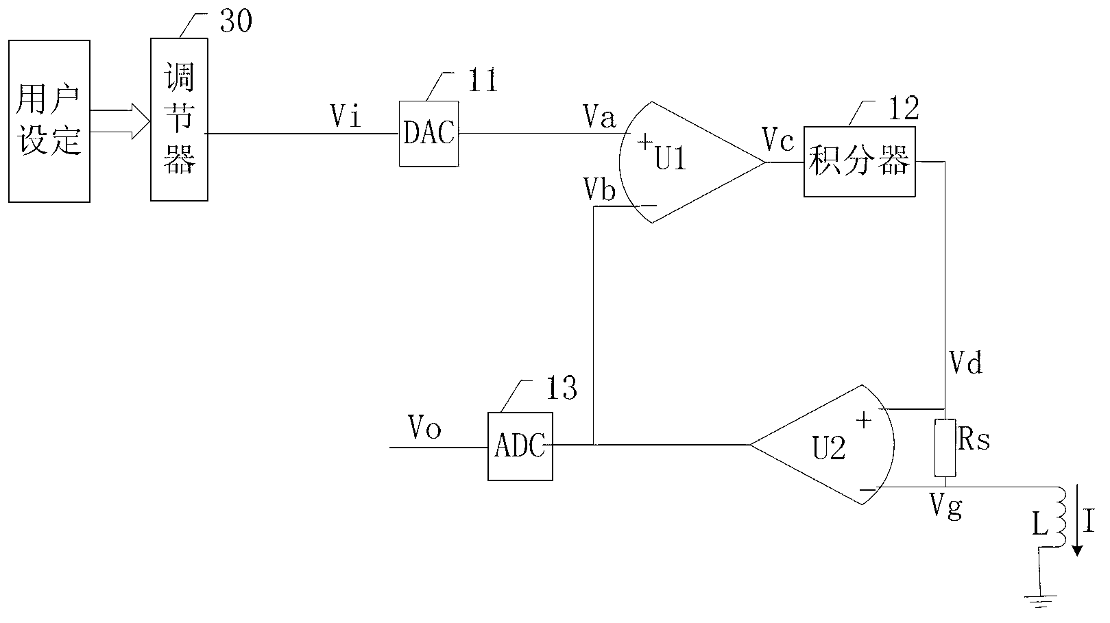
[0035] figure 1 It is a structural diagram of a solenoid valve driving circuit disclosed in the embodiment of the present application;

[0036] like figure 1 The solenoid valve driving circuit shown includes: a regulator 30, a digital-to-analog conversion circuit 11, a first differential amplifier U1, a second differential amplifier U2, an integrator 12, a sampling resistor Rs and an analog-to-digital conversion circuit 13, wherein:

[0037] The output end of the regulator 30 is connected with the input end of the digital-analog conversion circuit 11; the output end of the digital-analog conversion circuit 11 is connected with the non-inverting input end of the first differential amplifier U1; the output end of the first differential amplifier U1 is connected with the integral The input terminal of the device 12 is connected; the output terminal of the integrator 12 is connected with the non-inverting input terminal of the second differential amplifier U2; the output terminal...

Embodiment 2

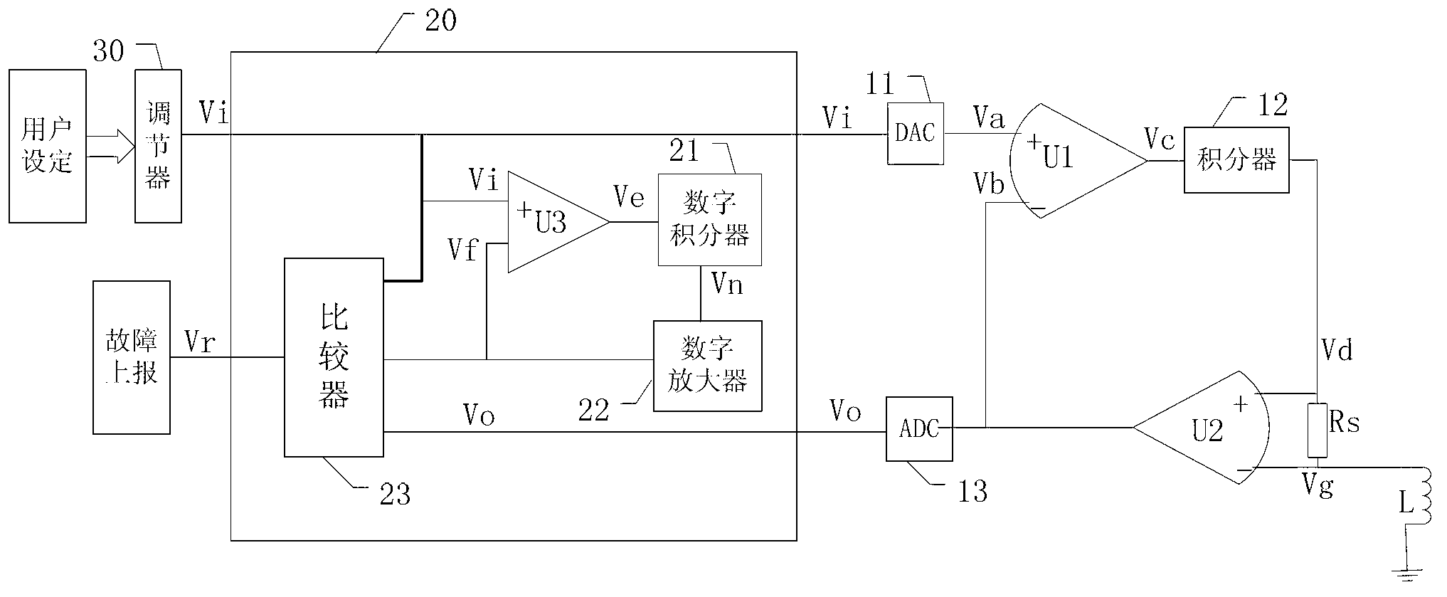
[0051] figure 1 It is a structural diagram of another driving circuit disclosed in the embodiment of the present application;

[0052] In this embodiment, a monitoring circuit is added on the basis of the driving circuit provided in the first embodiment, and the feedback signal is used as the signal to be detected by the monitoring circuit.

[0053] like figure 1 As shown, the increased monitoring circuit includes: digital subtractor U3, digital integrator 21, digital amplifier 22, comparison circuit 23, wherein:

[0054] The digital subtractor U3, the digital integrator 21 and the digital amplifier 22 form an inertial analog circuit, which is used to simulate the inertial characteristics of the driving circuit, and is used to simulate the inertial characteristics of the solenoid valve driving circuit. The time constant of the digital inertial circuit is set to be greater than that of the solenoid valve driving circuit. The time constant of the circuit.

[0055] The positiv...


PUM


Abstract

The invention discloses a driving circuit which is used for driving an electromagnetic valve in a turbine system. The driving circuit comprises a first differential amplifier, an integrator, a second differential amplifier and a sampling resistor, wherein the input end of the integrator is connected with the output end of the first differential amplifier, the normal phase input end of the second differential amplifier is connected with the output end of the integrator, the sampling resistor is connected between the normal phase input end and the inverted phase input end of the second differential amplifier, the inverted phase input end of the second differential amplifier serves as the current output end of the driving circuit, and the output end of the second differential amplifier is connected with the inverted phase input end of the first differential amplifier. A negative feedback adjusting loop is formed by the sampling resistor and the second differential amplifier. According to the driving circuit, after gains of the second differential amplifier and the resistance valve of the sampling resistor are determined, the output current solely depends on the voltage at the normal phase input end of the first differential amplifier under the effect of a negative feedback circuit, the output driving current is stable, and requirements of the turbine system in a power plant for the driving circuit of the electromagnetic valve can be met.

Description

technical field [0001] The present application relates to the technical field of speed control of steam turbines, and more specifically, relates to a solenoid valve driving circuit. Background technique [0002] In the steam turbine system of a power plant, the speed of the steam turbine is required to be constant, and the speed of the steam turbine depends on the effective value of the current driving the steam regulating valve. Therefore, in order to keep the speed of the steam turbine constant, the solenoid valve controlling the steam flow must have a stable driving current. [0003] At present, there is a solenoid valve driving circuit, which realizes the current generation through the pulse width adjustment framework feedback system, but the fluctuation of the generated current is relatively large, which is only suitable for the fuel injection system of the internal combustion engine, and cannot meet the requirements of the steam turbine system of the power plant drive...

Claims


Application Information

Patent Timeline
Patent Type & Authority Applications(China)
IPC IPC(8): F01D17/24
Inventor 李小卿屠昌锋孙咸平韩宝林王栋
Owner HANGZHOU HOLLYSYS AUTOMATION
Why Eureka
Try Eureka