Method capable of switching between different display modes and display device

A display device and display panel technology, which is applied in static indicators, optics, instruments, etc., can solve the problem of fewer display devices to switch.

Active Publication Date: 2013-09-11
BOE TECH GRP CO LTD
View PDF7 Cites 23 Cited by
  • Summary
  • Abstract
  • Description
  • Claims
  • Application Information

AI Technical Summary

Problems solved by technology

[0006] At present, there are relatively few display devi

Method used


Image

  • Method capable of switching between different display modes and display device
  • Method capable of switching between different display modes and display device
  • Method capable of switching between different display modes and display device

Examples


Embodiment 1

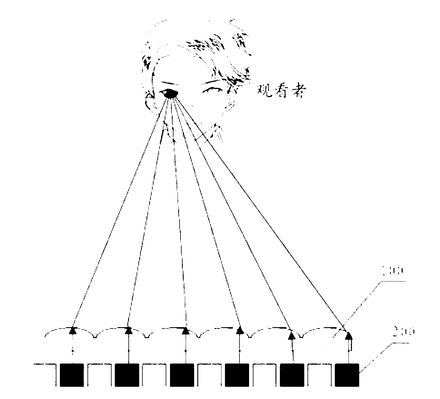
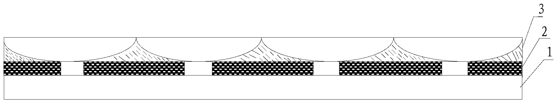
[0057] see image 3 , the display device includes:

[0058] display panel 1;

[0059] A slit grating device 2 located on the light-emitting side of the display panel 1;

[0060] A liquid crystal lens 3 located on the light emitting side of the slit grating device 2;

[0061] The slit grating device can make the display device form a 3D effect. The liquid crystal lens equivalently forms a concave lens effect when the display device performs dual-view display, and diffuses the first image and the second image emitted by the display panel to the first viewing area and the second viewing area respectively, and the When the display device performs 3D display, the liquid crystal lens equivalently forms the effect of a plane light-transmitting glass, and transmits the left-eye image and the right-eye image emitted by the display panel.

[0062] The display device provided in Embodiment 1 realizes the switching method between 3D and dual-view display specifically including:

[00...

Embodiment 2

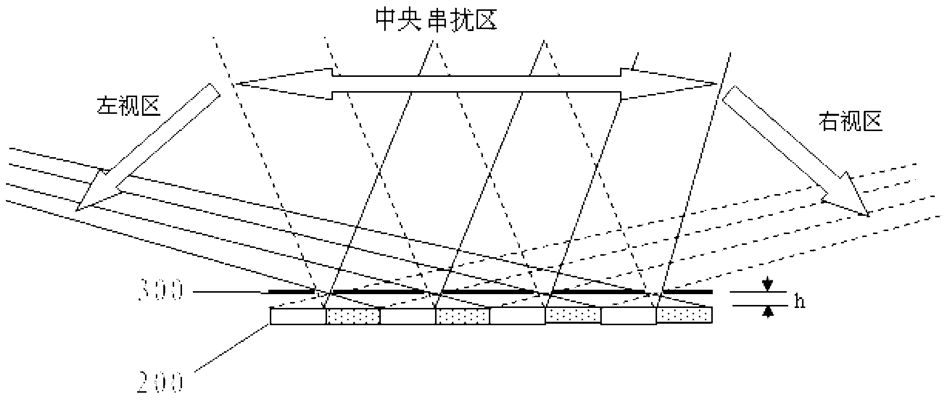
[0083] see image 3 , the display device includes:

[0084] display panel 1;

[0085] A slit grating device 2 located on the light-emitting side of the display panel 1;

[0086] A liquid crystal lens 3 located on the light emitting side of the slit grating device 2;

[0087] Wherein, the slit grating device can enable the display device to form a double-view effect; the liquid crystal lens is equivalent to forming a plane light-transmitting glass effect when the display device performs double-view display, and the first light emitted by the display panel The first image and the second image are transmitted; the liquid crystal lens equivalently forms a convex lens effect when the display device performs 3D display, and injects the left eye image and the right eye image emitted by the display panel into the left eye viewing area and the right eye image respectively. eye area.

[0088] The display device provided in Embodiment 2 implements a switching method between 3D and du...


PUM


Abstract

An embodiment of the invention provides a method capable of switching between different display modes and a display device, and particularly provides a method capable of switching between 2D (two-dimensional) display, 3D (three-dimensional) display and double-vision display and a display device. The display device comprises a display panel, a slit grating device positioned on a light-emitting side of the display panel and a liquid crystal lens on a light-emitting side of the slit grating device. The slit grating device is capable of enabling the display device to form a 3D effect. The liquid crystal lens equivalently forms a concave lens effect when double-vision display is performed by the display device so as to diffuse a first image and a second image sent by the display panel to a first visual area and a second visual area respectively, and the liquid crystal lens equivalently forms a plane light-transmitting effect when 3D display is performed by the display device so as to transmit a left eye image and a right eye image sent by the display panel.

Description

technical field [0001] The present invention relates to the field of display technology, in particular to a method and a display device capable of switching between different display modes. Background technique [0002] In the field of display technology, the display modes of display devices are classified according to their functions and at least include two-dimensional (2D) display mode, three-dimensional (3D) display mode and dual-view display mode. [0003] In daily life, people observe external scenes with a three-dimensional sense of space through their eyes. The reason why human eyes can distinguish three-dimensional (3D) image effects is that the two eyes have an interpupillary distance of about 60 mm, and the position difference generated by this interpupillary distance is binocular parallax. The two images seen by the binoculars with parallax are fused by the visual cortex of the human brain to produce a three-dimensional effect. 3D display technology is to use t...

Claims


Application Information

Patent Timeline
IPC IPC(8): G02B27/22G02B30/31
CPCG09G2320/0209H04N13/305G09G3/003G09G3/36G09G3/38G09G2320/0613G09G2320/068G02B30/31H04N13/312H04N13/354H04N2013/405G02B30/27G09G3/3659
Inventor 武延兵
Owner BOE TECH GRP CO LTD
Why Eureka
Try Eureka