
Locking mechanism of power switch

A locking mechanism and power switch technology, which is applied to the parts of protection switches, electric switches, protection switches, etc.

Active Publication Date: 2016-09-07
SIEMENS AG
View PDF4 Cites 0 Cited by
  • Summary
  • Abstract
  • Description
  • Claims
  • Application Information

AI Technical Summary

Problems solved by technology

Known locking mechanisms for the cut-off position are thus often only available for a limited number of locking mechanisms with always the same locking mechanism kinematic behavior

Method used


Image

  • Locking mechanism of power switch
  • Locking mechanism of power switch
  • Locking mechanism of power switch

Examples


Embodiment Construction

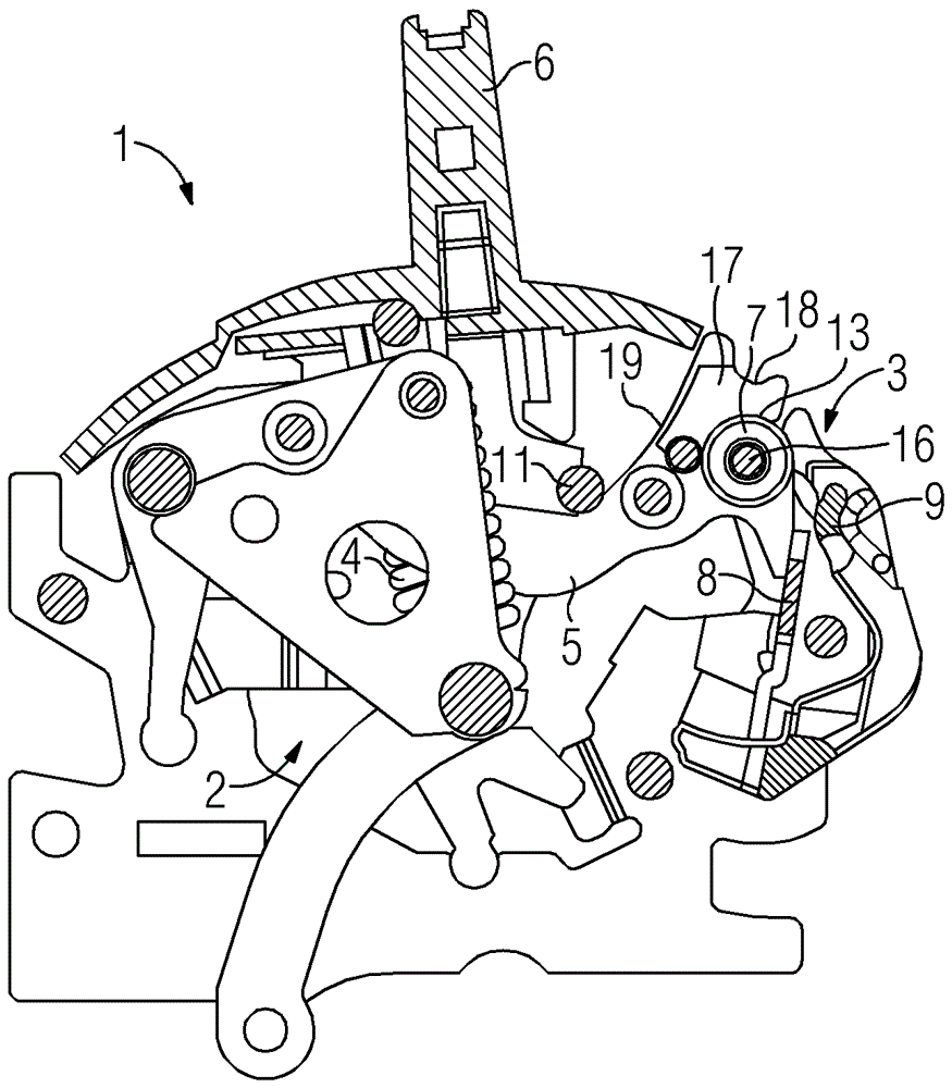
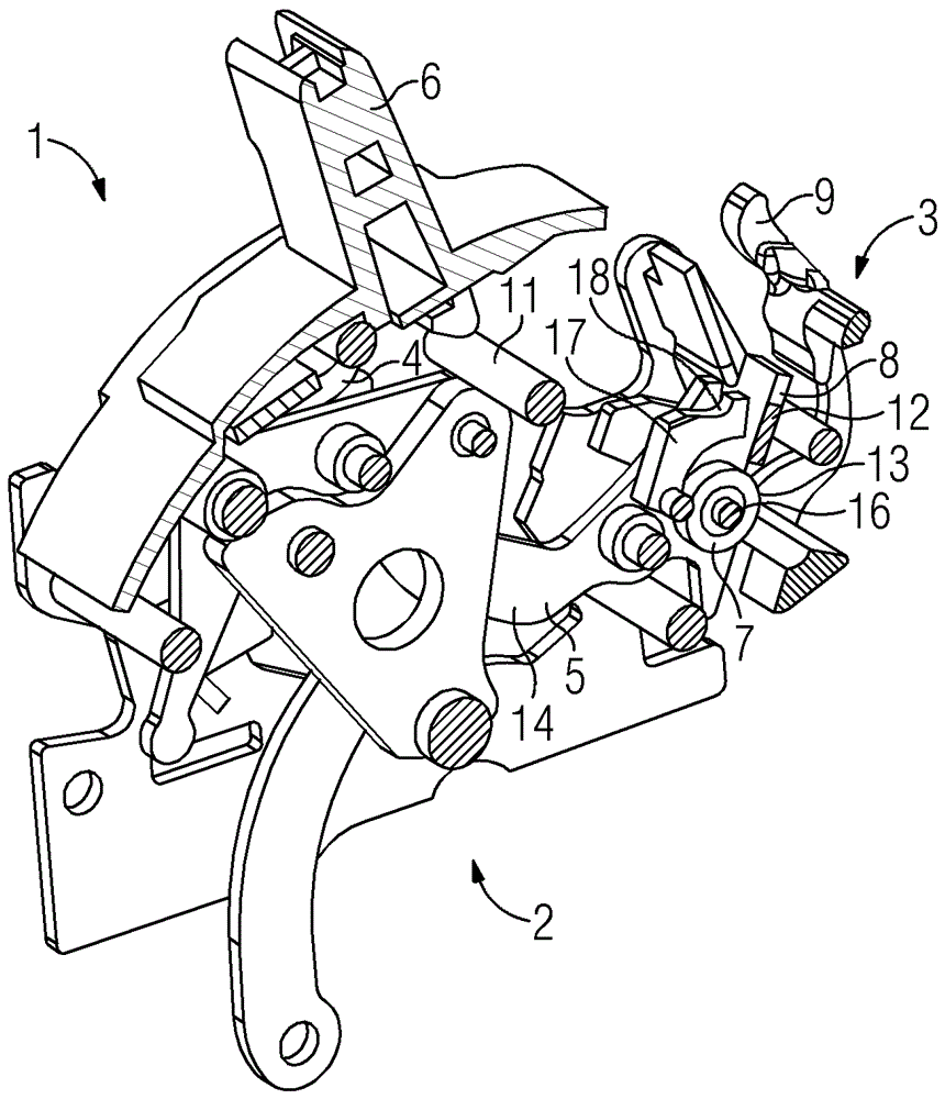
[0029] figure 1 The locking mechanism 1 of the power switch is shown in a perspective view. The locking mechanism 1 shown here has two main standard components, namely a switching mechanism 2 and a release mechanism 3 . Via the switching mechanism 2 , the electrical switching contacts of the power switch are thus in operative connection with a spring 4 serving as an energy store, and when the contacts are closed, the spring 4 is tensioned and at the time of tripping The energy stored in the spring 4 is released when the locking mechanism 1 is described, so that the contacts are disconnected by the elastic force acting on them.

[0030] In order, on the one hand, to securely hold the spring 4 in the tensioned state and, on the other hand, to be able to ensure a reliable and rapid release of the locking mechanism, the release mechanism 3 is provided.

[0031] The connection between the switching mechanism 2 with tension spring 4 and the release mechanism 3 is established via a...


PUM


Abstract

The invention relates to a power switch having a latching mechanism (1) with a switching mechanism (2) for opening and closing a switching contact that is operatively connected to a tensioning element (4). and a release mechanism (3) via which the tensioning element (4) can be switched from a tensioned state to an at least largely untensioned state on the basis of a tripping signal such that all The switch contacts are thereby opened, wherein the tensioning element (4) is indirectly coupled to a tensioning rod (5) which can ) position for locking or unlocking and the tensioning lever has a locking device, by means of which the tensioning lever (5) is also prevented in the disengaged position of the locking mechanism (1) despite the unlocking signal The tripping of the locking mechanism (1), wherein the switch is open and the tensioning element (4) is tensioned in the shut-off position of the locking mechanism (1). The technical solution described is distinguished in that the locking device of the tension lever (5) has a rocker lever (17) which is fastened movably to the tension lever ( 5) on.

Description

technical field [0001] The invention relates to a power switch with a locking mechanism. Such a locking mechanism has, on the one hand, a switching mechanism for opening and closing the switching contacts which are in operative connection with the tensioning element, and on the other hand has a release mechanism, by means of which on the basis of a tripping signal The above-mentioned tensioning element can be switched from a tensioned state into an at least largely untensioned state in order to open the switching contacts in this way. Background technique [0002] Power switches are special switches usually designed for higher currents. These switches not only switch over operating currents and small overload currents, but also switch through higher overload currents and short-circuit currents in the event of a fault, hold these fault currents for a predetermined time and switch them off again. According to specific embodiments, the power switch is designed as a single-pol...

Claims


Application Information

Patent Timeline
Patent Type & Authority Patents(China)
IPC IPC(8): H01H3/32
CPCH01H71/1054H01H71/505H01H71/525H01H2071/506H01H2071/508H01H9/20
Inventor T.邦克S.皮尔克
Owner SIEMENS AG
Learn More